3.10. The Power Monitor
The Power Monitor measures and reports current power information and
communicates with the MAX II device on the board through the JTAG bus. A power
monitor circuit attached to the MAX II device allows you to measure the power that
the FPGA is consuming.
To start the application, click the Power Monitor icon in the Board Test System
application. You can also run the Power Monitor as a stand-alone application. The
PowerMonitor.bat and ClockController.bat reside in the <installer package>
\examples\board_test_system directory.
Note: You cannot run the stand-alone power application and the BTS application at the same
time.
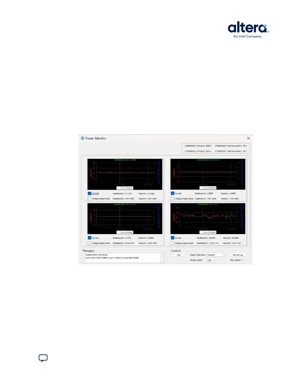
Figure 15. The Power Monitor
This window displays both LTC2990 current and temperature monitors. The left side
top and bottom quadrant shows U29 and the opposite side shows U30. Use the
available controls to show Current or Voltage Single-Ended, or both.
Single Chart Mode allows you to choose how you want the panes to display. You can
show only a single large pane, if needed.
Voltage Single-Ended shows the voltage value of each power rail:
3. Board Test System
683460 | 2024.11.20
Send Feedback
MAX
®
10 FPGA Development Kit User Guide
27