3.11. The Clock Controller
The MAX 10 FPGA development board Clock Controller application sets the
programmable oscillators to any frequency between 10 MHz and 810 MHz. The
frequencies support eight digits of precision to the right of the decimal point.
The Clock Controller communicates with the MAX II device on the board through the
JTAG bus. The programmable oscillators are connected to the MAX II device through a
2-wire serial bus.
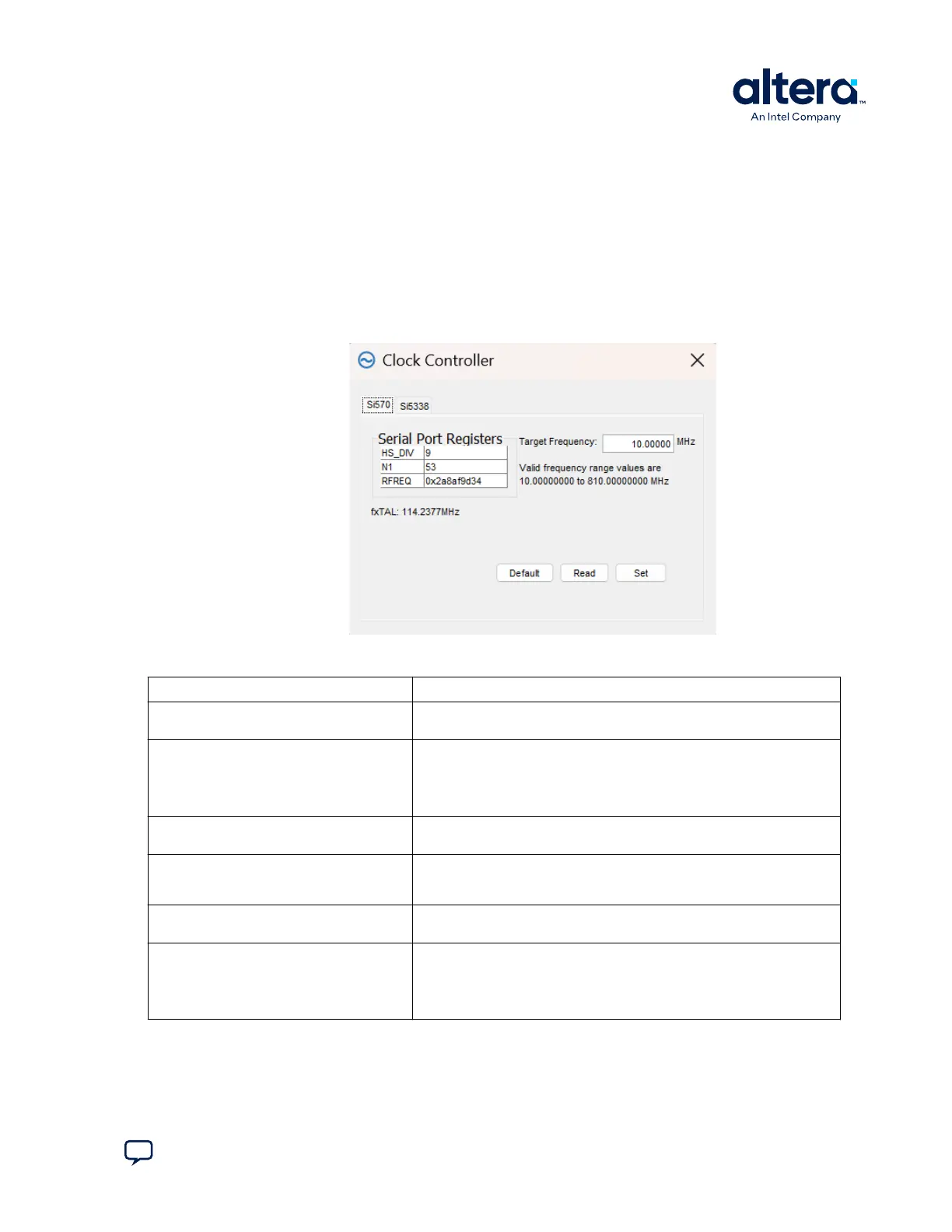
Figure 16. The Si570 Tab
Table 12. Controls on the Si570 Tab
Control Description
Serial Port Registers Shows the current values from the Si570 registers for frequency
configuration.
Target Frequency Allows you to specify the frequency (in MHz) of the clock. Legal values are
between 10 and 810 MHz with eight digits of precision to the right of the
decimal point. For example, 421.31259873 is possible within 100 parts per
million (ppm). The Target Frequency control works in conjunction with
the Set control.
fxTAL Shows the calculated internal fixed-frequency crystal, based on the serial
port register values.
Default Sets the frequency for the oscillator associated with the active tab back to
its default value. This can also be accomplished by power cycling the
board.
Read Reads the current frequency setting for the oscillator associated with the
active tab.
Set Sets the programmable oscillator frequency for the selected clock to the
value in the Target Frequency control for the programmable oscillators.
Frequency changes might take several milliseconds to take effect. You
might see glitches on the clock during this time. Altera recommends
resetting the FPGA logic after changing frequencies.
3. Board Test System
683460 | 2024.11.20
Send Feedback
MAX
®
10 FPGA Development Kit User Guide
29