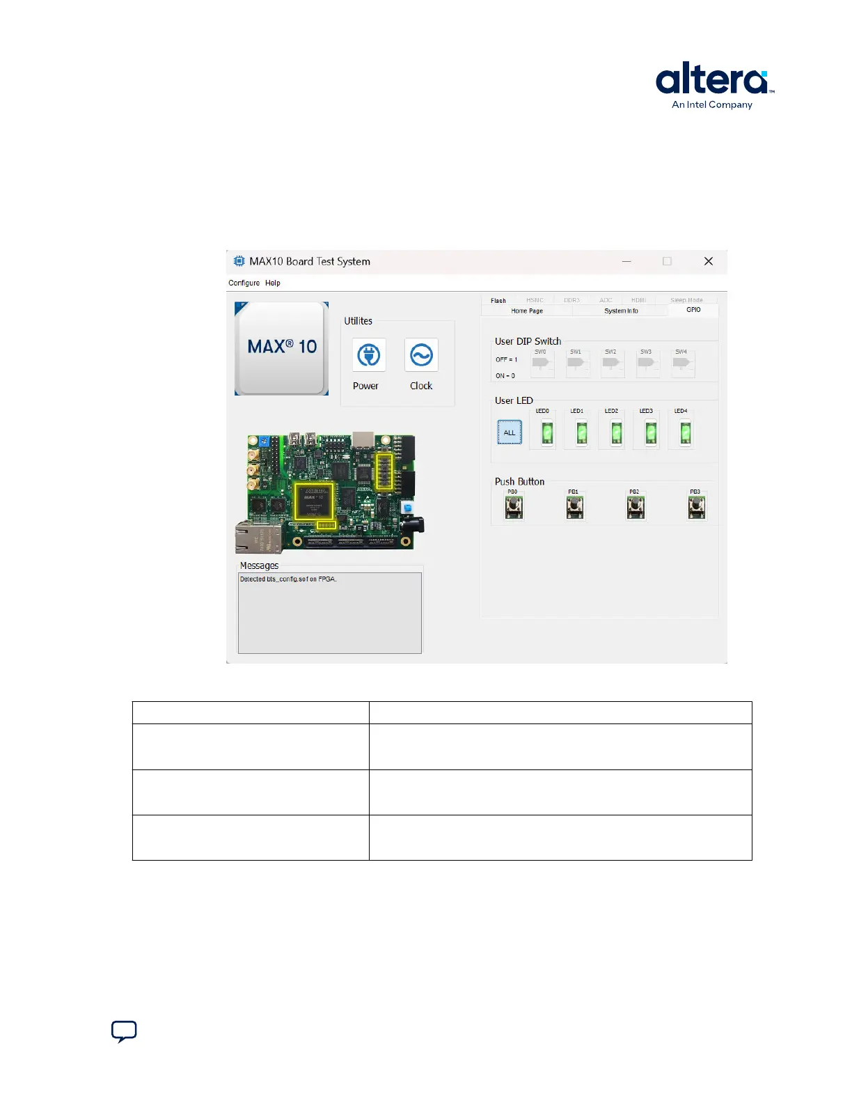
3.3. The GPIO Tab
The GPIO tab allows you to interact with all the general purpose user I/O components
on your board. You can read DIP switch settings, turn LEDs on or off, and detect push
button presses.
Figure 8. The GPIO Tab
Table 4. Controls on the GPIO Tab
Control Description
User DIP Switch Displays the current positions of the switches in the user DIP switch banks.
Change the switches on the board to see the graphical display change
accordingly.
User LED Displays the current state of the user LEDs for the FPGA. To toggle the
board LEDs, click the 0 to 4 buttons to toggle red or green LEDs, or click
the All button.
Push Button Read-only control displays the current state of the board user push
buttons. Press a push button on the board to see the graphical display
change accordingly.
3. Board Test System
683460 | 2024.11.20
Send Feedback
MAX
®
10 FPGA Development Kit User Guide
17