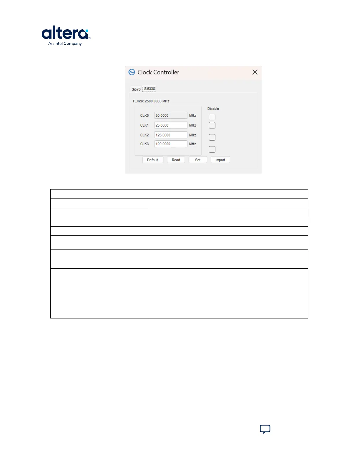
Figure 17. The Si5338 Tab
Table 13. Controls on the Si5338 Tab
Control Description
F_vco Displays the generating signal value of the voltage-controlled oscillator.
Registers Display the current frequencies for each oscillator.
Frequency Allows you to specify the frequency (in MHz) of the clock.
Disable Disable each oscillators as required.
Read Reads the current frequency setting for the oscillator associated with the
active tab.
Default Sets the frequency for the oscillator associated with the active tab back to
its default value. This can also be accomplished by power cycling the
board.
Set Sets the programmable oscillator frequency for the selected clock to the
value in the CLK0 to CLK3 controls. Frequency changes might take several
milliseconds to take effect. You might see glitches on the clock during this
time. Altera recommends resetting the FPGA logic after changing
frequencies.
Note: Changing CLK0 of Si5338 affects the Clock Controller and Power
Monitor GUIs. One clock from port CLK0 is used to drive the MAX II
device which as a 2-wire serial bus interface connected to SI570,
Si5338, and the power monitor.
3. Board Test System
683460 | 2024.11.20
MAX
®
10 FPGA Development Kit User Guide
Send Feedback
30