Package Mechanical Specifications
16 Thermal/Mechanical Specifications and Design Guide
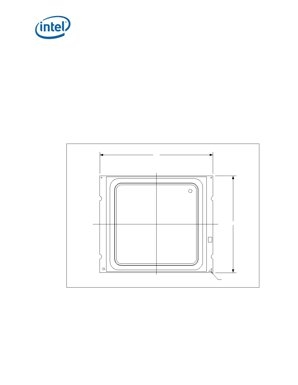
2.1.1 Package Mechanical Drawing
Figure 2-2 shows the basic package layout and dimensions. The detailed package
mechanical drawings are in Appendix D. The drawings include dimensions necessary to
design a thermal solution for the processor. These dimensions include:
1. Package reference with tolerances (total height, length, width, and so forth)
2. IHS parallelism and tilt
3. Land dimensions
4. Top-side and back-side component keep-out dimensions
5. Reference datums
6. All drawing dimensions are in mm.
7. Guidelines on potential IHS flatness variation with socket load plate actuation and
installation of the cooling solution is available in the Chapter 8.
2.1.2 Processor Component Keep-Out Zones
The processor may contain components on the substrate that define component
keep-out zone requirements. A thermal and mechanical solution design must not
intrude into the required keep-out zones. Do not contact the Test Pad Area with
conductive material. Decoupling capacitors are typically mounted to either the topside
or land-side of the package substrate. See Figure D-1 and Figure D-2 for keep-out
zones. The location and quantity of package capacitors may change due to
manufacturing efficiencies but will remain within the component keep-in.
Figure 2-2. Package View
 Loading...