Thermal/Mechanical Specifications and Design Guide 25
LGA2011-0 Socket
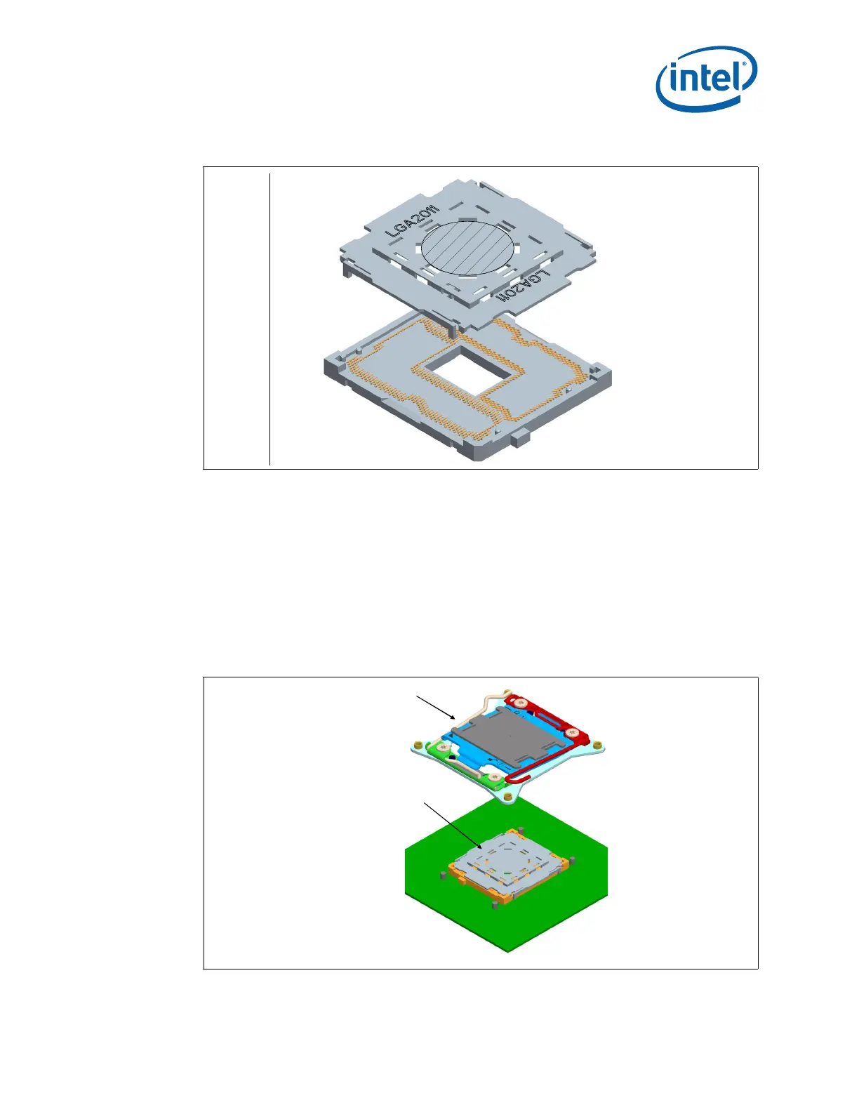
As indicated in Figure 3-8, the pick and place (PnP) cover remains on the socket during
ILM installation. Once the ILM with its cover is installed, Intel is recommending the PnP
cover be removed to help prevent damage to the socket contacts. To reduce the risk of
bent contacts the PnP Cover and ILM Cover were designed to not be compatible. See
Section 4.3 for additional information on ILM assembly to the board.
Cover retention must be sufficient to support the socket weight during lifting,
translation, and placement (board manufacturing), and during board and system
shipping and handling. Covers can be removed without tools.
The pick and place covers are designed to be interchangeable between socket
suppliers.
Note: Figure is representative and may not show the most current revision of parts.
Figure 3-7. LGA2011-0 Pick and Place Cover
Figure 3-8. Pick and Place Cover
 Loading...