Thermal/Mechanical Specifications and Design Guide 47
Thermal Management Specifications
1. The ambient temperature is measured at the inlet to the processor thermal solution.
2. This column can be expressed as a function of T
AMBIENT
by the following equation:
Y
CA
= 0.18 + (43.4 - T
AMBIENT
) x 0.013
3. This column can be expressed as a function of T
AMBIENT
by the following equation:
Y
CA
= 0.18 + (43.4 - T
AMBIENT
) x 0.0077
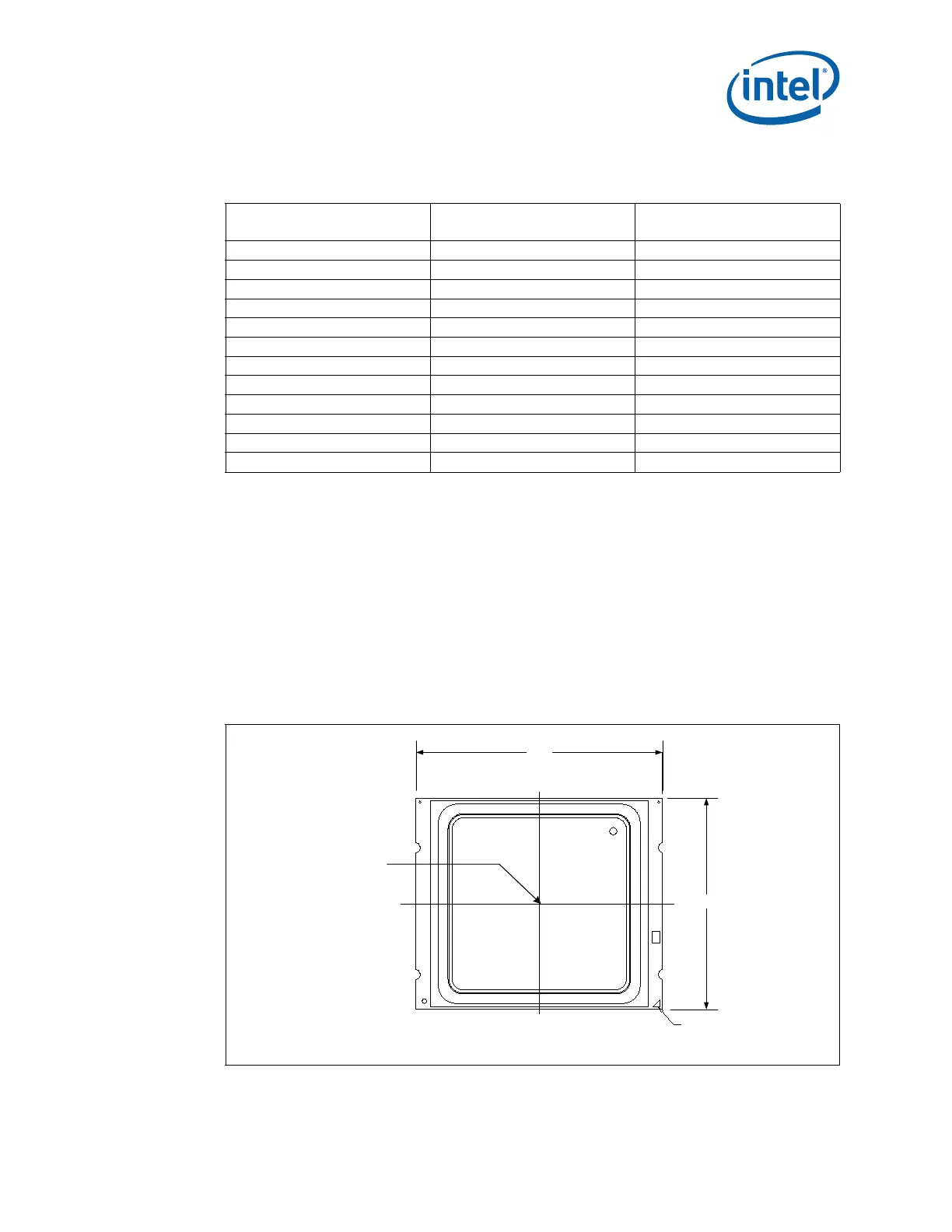
6.1.4 Thermal Metrology
The maximum TTV case temperatures (T
CASE-MAX
) specified in Ta b le 6 - 2 is measured at
the geometric top center of the TTV integrated heat spreader (IHS). Figure 6-2
illustrates the location where T
CASE
temperature measurements should be made. A
dimensioned drawing for milling the groove to place the thermocouple on the IHS can
be found in Appendix E.
29.0 0.368 0.291
28.0 0.381 0.298
27.0 0.394 0.306
26.0 0.407 0.314
25.0 0.420 0.322
24.0 0.433 0.329
23.0 0.446 0.337
22.0 0.459 0.345
21.0 0.472 0.352
20.0 0.485 0.360
19.0 0.498 0.368
18.0 0.511 0.375
Table 6-3. Thermal Solution Performance above T
CONTROL
for the Intel
®
Core™ i7-3960X,
i7-3970X Processor Extreme Edition, Intel
®
Core™ i7-3930K Processor, and
Intel
®
Core™ i7-3820 Processor (Sheet 2 of 2)
T
AMBIENT
1
Ψ
CA
at
DTS = T
CONTROL
2
Ψ
CA
at
DTS = -1
3
Figure 6-2. Case Temperature (T
CASE
) Measurement Location
52.5
45.0
Pin 1
Measure Tcase
at the Geometric
Center of the
Package