Thermal/Mechanical Specifications and Design Guide 99
Thermal Solutions
8.3 Geometric Envelope for the Intel
®
Reference ATX
Thermal Mechanical Design
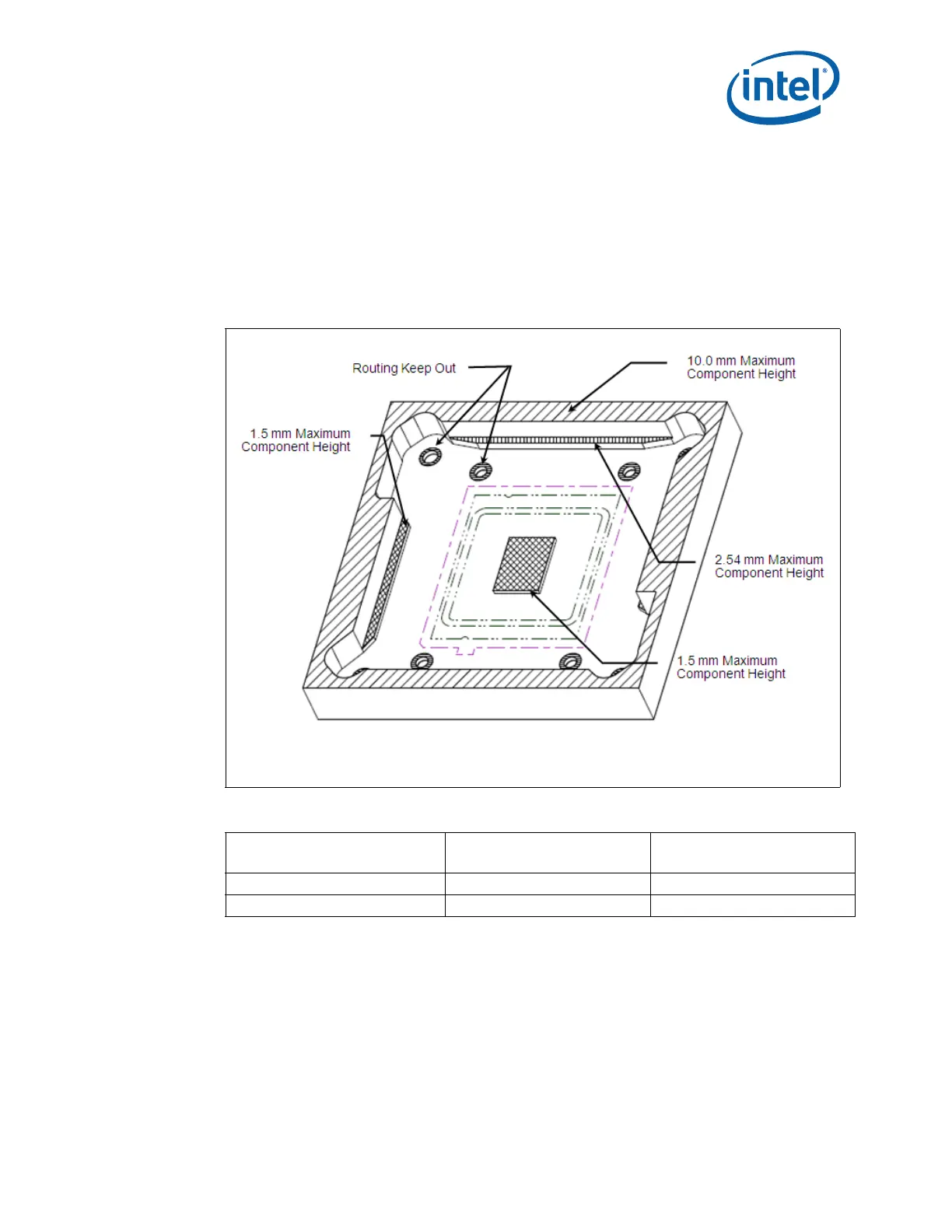
Figure 8-3 shows a 3-D representation of the board component keep out for the
reference ATX thermal solution. A fully dimensioned drawing of the keepout information
is available at Figure A-1 and Figure A-2 in Appendix A. A PDF version of these
drawings is available as well as a 3-D IGES model of the board level keep out zone is
available. Contact your field sales representative for these documents.
The chassis obstruction height allows for appropriate fan inlet airflow to ensure fan
performance, and therefore overall cooling solution performance.
Figure 8-3. ATX KOZ 3-D Model Primary (Top) Side
Note: All Maximum Component Heights are post reflow / assembly
Table 8-2. Reference Heat Sink Clearance above the Motherboard
Heat Sink
Max Heat Sink Height above
the motherboard
Chassis Obstruction Height
above motherboard
Tall Heat Pipe Heat Sink (T-HPHS) 130mm [5.51 inches] N/A side inlet for airflow
Radial Fin Copper Core (DRA-A) 71.12mm [2.8 inches] 81.28mm [3.2 inches]
 Loading...