Thermal/Mechanical Specifications and Design Guide 87
PECI Interface
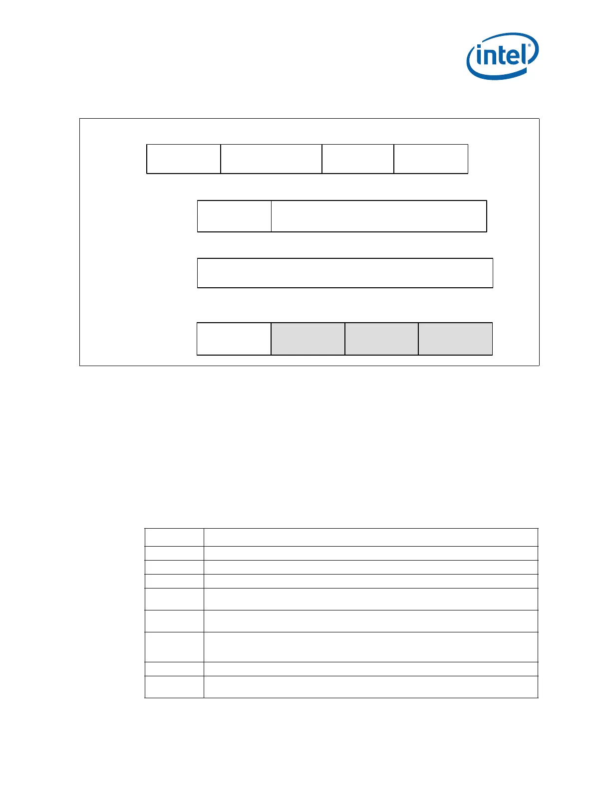
The 3-byte PCI configuration address and write data field defined in Figure 7-43 are
sent in standard PECI ordering with LSB first and MSB last.
7.1.4.12.2 Supported Responses
The typical client response is a passing FCS, a passing Completion Code and valid data.
Under some conditions, the client’s response will indicate a failure.
The PECI client response can also vary depending on the address and data. It will
respond with a passing completion code if it successfully submits the request to the
appropriate location and gets a response. Exactly what the receiving agent does with
the data or how it responds is up to that agent and is outside the scope of PECI 3.0.
Figure 7-43. WrPCIConfigLocal()
Byte
Definition
01 2
FCS
3
Completion
Code
AW FCS
12
Byte #
FCS
13 14 15
Write Length
{0x07, 0x08, 0x0a}
Host ID[7:1] &
Retry[0]
4
8
Read Length
0x01
56
Cmd Code
0xe5
10
11
Client Address
9
LSB PCI Configuration Address MSB
LSB Data (1, 2 or 4 bytes) MSB
7
Table 7-15. WrPCIConfigLocal() Response Definition
Response Meaning
Bad FCS Electrical error or AW FCS failure
Abort FCS Invalid command formatting (mismatched RL/WL/Command Code)
CC: 0x40 Command passed, data is valid.
CC: 0x80
Response timeout. The processor was not able to generate the required response in a timely
fashion. Retry is appropriate.
CC: 0x81
Response timeout. The processor is not able to allocate resources for servicing this command
at this time. Retry is appropriate.
CC: 0x82
The processor hardware resources required to service this command are in a low power
state. Retry may be appropriate after modification of PECI wake mode behavior if
appropriate.
CC: 0x90 Unknown/Invalid Request
CC: 0x91
PECI control hardware, firmware or associated logic error. The processor is unable to process
the request.