68
Intermec EasyCoder 201 II – Technical Manual
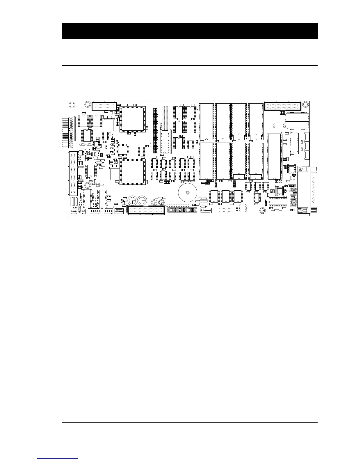
The CPU board contains a number of jumpers and socket-mounted
circuits, which decide how the printer will work.
Before touching the CPU board, carefully read the following
instructions:
• Take precautions to prevent electrostatic discharge.
• Keep in mind that the RAM's and the clock circuit are battery
backed-up. Therefore, there is a risk of short-circuit if any
conductive tools are used on the CPU board.
• When adding or replacing any socket-mounted circuits, make
sure that their “front” markings are pointing in the direction
indicated by the illustration above.
• EPROM- or RAM packages, that are smaller than their sockets,
must be fitted as illustrated above (see IC-5 – IC-8).
CPU Board
ELECTRONICS, cont'd.
IC-5 IC-7
IC-1 IC-3
IC-6 IC-8
IC-2 IC-4
IC -14
P-14
IC-12
.30
971700,10
1
LAYER
P-21P-22
P-24
3.6V 110 mAh
3/V110R
P-10