86
Intermec EasyCoder 201 II – Technical Manual
INTERFACES, cont'd.
Continued!
RS 422/485 Interface Board,
cont'd.
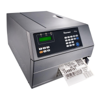
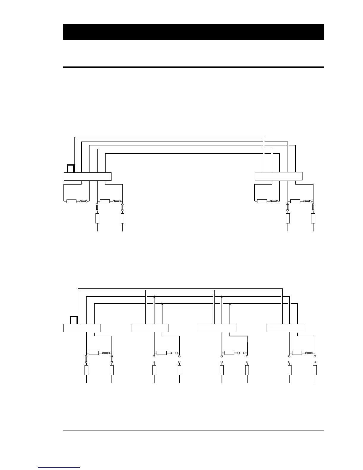
The illustrations below show how the voltage reference straps and
terminating resistor straps should be fitted on the RS 422/485
interface boards. When a computer is connected to the line or loop,
the same principles apply. Refer to the computer manuals for
information on how to appoint the computer “master” and how to
set the termination.
100 ohm
17
+
19
-
21 7
+
19
-
21
7
+
19
-
21
7
+
19
-
21
Screen
Screen
Screen
Screen
P-10
P-8
P-2
P-9
+VEE GNDE
100 ohm
P-10
P-8
P-2
P-9
+VEE GNDE
100 ohm
P-10
P-8
P-2
P-9
+VEE GNDE
PRINTER
100 ohm
P-10
P-8
P-2
P-9
+VEE GNDE
PRINTERPRINTERPRINTER (master)
RS 485 MULTIDROP LOOP
(w. printer as master unit)
Screened twisted 2-line cable (approx. 50 pf/m)
P-8 and P-9 strapped on master unit.
P-10 strapped on first unit.
Connection P-2 pin 7 to Chassis GND
(e.g. P-2 pin 1) on one unit only.
No straps No straps P-10 strapped on last unit.
100 ohm100 ohm
P-10P-11
P-8P-9
+VEE GNDE
100 ohm100 ohm
17
+
19
-
21
+
15
-
17 7
+
19
-
21
+
15
-
17
Screen
Screen
P-10P-11
P-8
P-2
P-9
+VEE GNDE
P-2PRINTER
RS 422 POINT-TO-POINT
(printer to printer)
Screened twisted 4-line cable (approx. 50 pf/m)
P-8 and P-9 strapped on both units.
P-10 and P-11 strapped on both units.
Connection P-2 pin 7 to Chassis GND
(e.g. P-2 pin 1) on one unit only.
PRINTER
P-8 and P-9 strapped on both units.
P-10 and P-11 strapped on both units.