93
Intermec EasyCoder 201 II – Technical Manual
INTERFACES, cont'd.
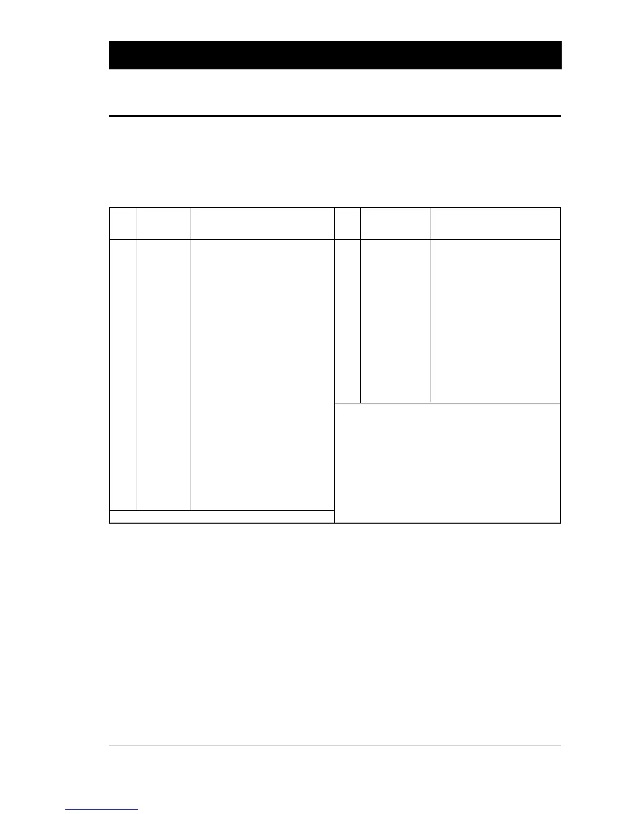
Connector Configuration
"uart3:" is a DB25 female connector.
The In/Out connector is a DB15 female connector.
The mounting holes are connected to chassis ground.
Industrial Interface Board,
cont'd.
Pin "uart3:" Remarks Pin In/Out connector Remarks
DB25 female DB15 female
1 GNDC Cable shield 1 OUT 201 See example on next page
2 TXDB Transmitted data from printer 2 OUT 201
3 RXDB Received data to printer 3 OUT 202
4 RTSB RTS from printer 4 OUT 202
5 CTSB CTS to printer 5 OUT 203
6 DRSB DSR to printer 6 OUT 203
7 GNDI Signal ground 7 OUT 204
8 – not used 8 OUT 204
9 – not used 9 IN 101 See example on next page
10 – not used 10 IN 101
11 – not used 11 IN 102
12 – not used 12 IN 102
13 – not used 13 IN 103
14 – not used 14 IN 104
15 – not used 15 IN 103/104
16 +5VEXT + 5V max 200 mA*
17 – not used
18 – not used
19 – not used
20 DTRB DTR permanently high
21 – not used
22 – not used
23 – not used
24 – not used
25 – not used
*/. If strap fitted on P-1
OUT signals are controlled by means of
PORTOUT (<nexp>) ON|OFF statements.
IN and OUT signals are read by means of
PORTIN (<nexp>) functions.
Also see Intermec Fingerprint manuals.