85
Intermec EasyCoder 201 II – Technical Manual
P6
P3
P11
S1
S2
S3
S4
S5
P10
P9
P8
MASTER
END
P7
2-WIRE
4-WIRE
5V-EXT
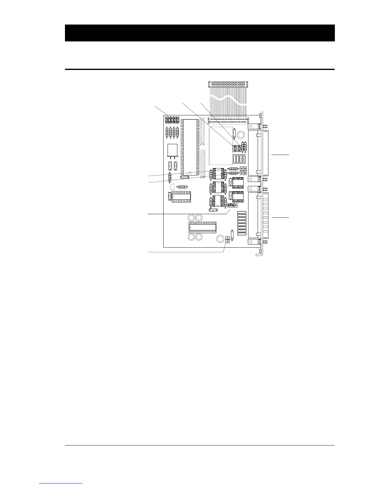
INTERFACES, cont'd.
RS 422/485 Interface Board,
cont'd.
Continued!
The following straps are used to set up the desired interface:
Communication Port "uart2:" (RS 422/485)
P-3 Selects 2- or 4-wire communication (see text on board).
P-7 Selects address for the printer (only used in RS 485
connection with "prot. addr. enable") according to the
table later in this chapter.
P-8, P-9 Voltage reference straps.
RS 422: P-8 and P-9 should be strapped on both units.
RS 485: P-8 and P-9 should be strapped on "master" unit.
Usually, the host computer is master.
P-10 100 Ω terminating resistor. Should be strapped on the first
and last units, regardless of RS 422 or RS 485.
P-11 100 Ω terminating resistor. Should be strapped on both
units in an RS 422 line.
Communication Port "uart3:" (RS 232C)
P-6 Connects +5V to pin 16 on "uart3:". Max 200 mA.
Warning! Be careful not to enable the external +5V
unintentionally, which may cause harm to the terminal,
computer or other device connected to this port!
"uart3:"
"uart2:"
P-7
P-8
P-9
P-11 P-10
P-6
P-3