Goodrive300-LIFT series inverter Function parameters
-49-
Detailed instruction of parameters
3: Down operation
4: Fault output
5: Zero speed running
6: Ready for running
7: Braking control
8: Contactor control
9: Frequency arrival
10: Frequency detection threshold (FDT) output
11: FDT reverse output
12: Reserved
13: Light-load direction detection completed
14: Down as the light-load direction detection
result
15: Up as the light-load direction detection result
16: Running 1 (excluding current withdrawal)
17: STO opereation
18: SPI fault output
19: UPS control signal output (for India)
20: Reserved
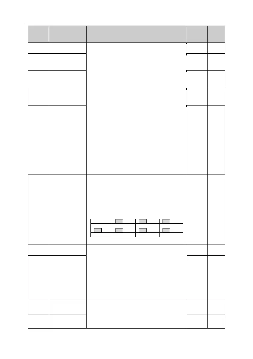
Polarity of output
terminals
The function code is used to set the pole of the
output terminal.
If the current bit is set to 0, output terminal is
positive. If the current bit is set to 1, output
terminal is negative.
0: Running speed
1: Set speed
2: Running rotation speed
3: Output current
4: Output voltage
5: Output power
6: Output torque
7: AI1 input value
8: AI2 input value
9–14: Reserved
HDO high-speed
pulse output
The above function codes define the relative
relationship between the output value and
AO1 output of
lower limit
 Loading...
