Goodrive300-LIFT series inverter Keypad operation procedure
-30-
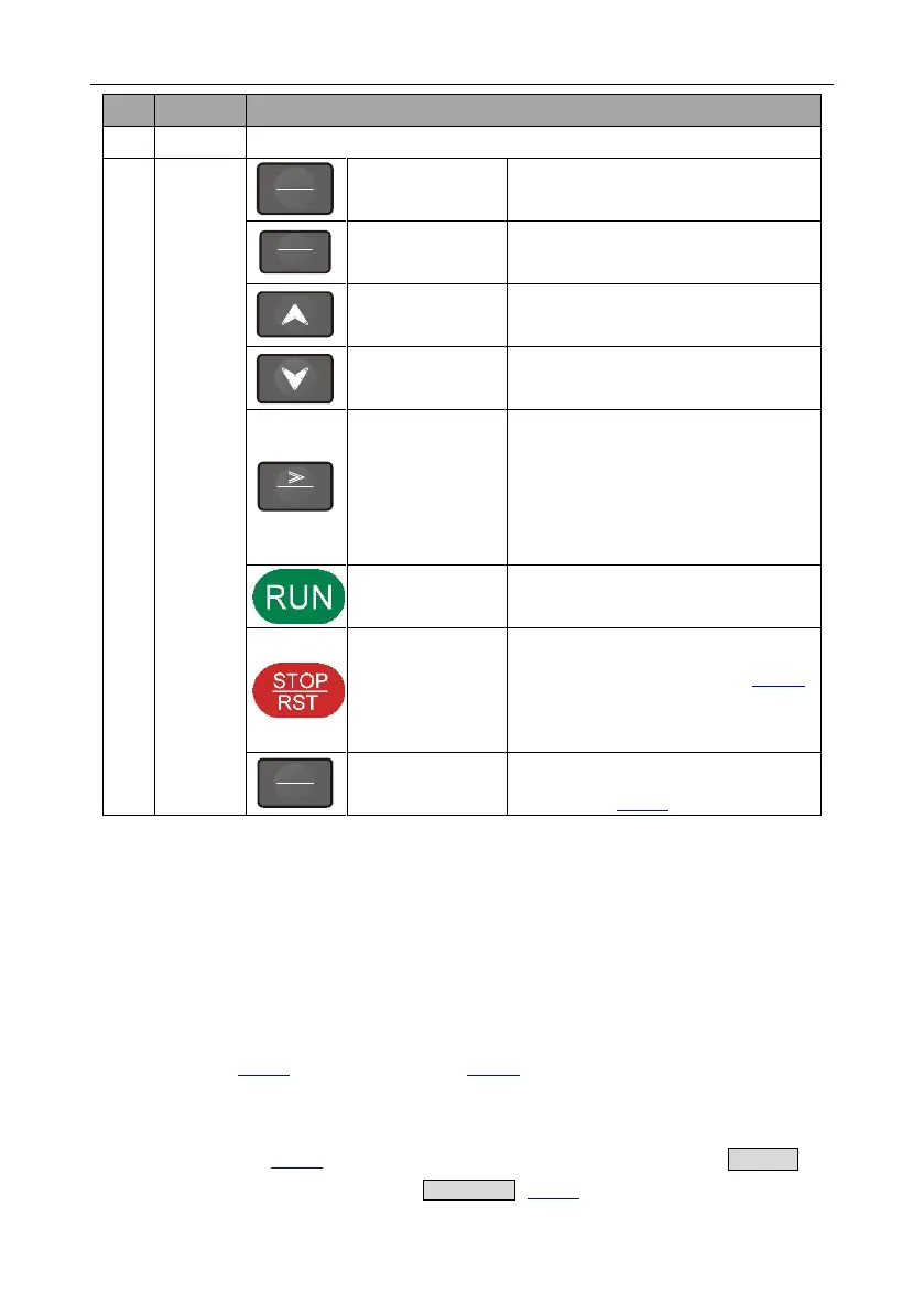
Enter or escape from the first level menu
and remove the parameter quickly.
Enter the menu step-by-step.
Confirm parameters.
Increase data or function code
progressively.
Decrease data or function code
progressively.
Move right to select the displaying
parameter circularly in stopping and
running mode.
Select the parameter modifying digit
during the parameter modification.
This key is used to operate on the
inverter in key operation mode.
This key is used to stop in running state
and it is limited by function code P07.05
This key is used to reset all control
modes in the fault alarm state.
The function of this key is confirmed by
function code P07.04.
5.3 Keypad displaying
The keypad displaying state of Goodrive300L series inverters is divided into stopping state parameter,
running state parameter, function code parameter editing state and fault alarm state and so on.
5.3.1 Displayed state of stopping parameters
When the inverter is in the stopping state, the keypad will display stopping parameters as shown in
Figure 5-2.
In the stopping state, various kinds of parameters can be displayed. Select the parameters to be
displayed or not by P07.08. See the instructions of P07.08 for the detailed definition of each bit.
In the stopping state, there are 9 stopping parameters can be selected to be displayed or not. They
are: set speed, set frequency, bus voltage, input terminals state, output terminals state, AI1, AI2, and
magnetic pole position. P07.08 determines whether to display the parameters by bit. 》/SHIFT can
shift the parameters form left to right, while QUICK/JOG (P07.04=2) can shift the parameters form
 Loading...
