Goodrive300-LIFT series inverter Installation guide
-24-
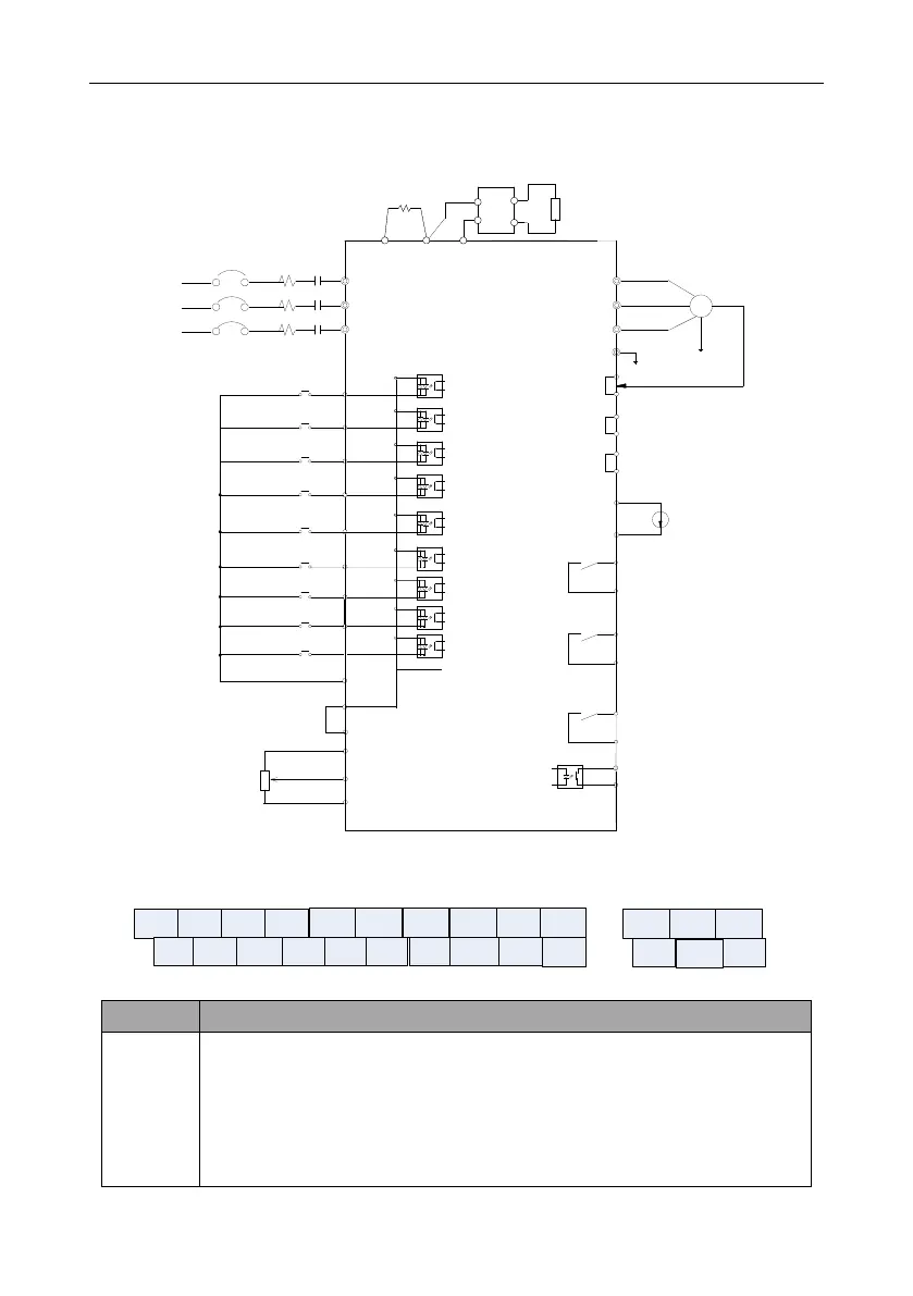
4.3.5 Connection diagram of control circuit
GD300L inverters
special for lifts
Multi-function input terminal 1
Multi-function input terminal 2
Multi-function input terminal 3
Multi-function input terminal 4
Multi-function input terminal 5
Multi-function input terminal 6
S6
S5
S4
S3
S2
S1
COM
Analog output
0-10V/4-20mA
+24V
Relay 1 output
24V
S7
Multi-function input terminal 7
GND
AI1
+10V
Analog speed
adjustment
0~10V/0-20mA
PW
R03C
Y1
CME
AO1
GND
High-speed input terminal
HDI
Multi-function input terminal 8
S8
R03A
R02C
R02A
R01C
R01A
Relay 2 output
Relay 3 output
CN3
M
U
V
W
PE
R
S
T
P1
(+) (-)
P1
(+)
DC reactor
(built-in for
18.5-30kW)
(-)
-
Braking resistor
+
RB2
RB1
(Inverters of 18.5kW or
higher connect
external braking units)
3PH
50Hz/60Hz
380V(-15%)
~440V(+10%)
CN13
CN14
Multi-function expansion
card interface
External keypad interface
Open collector output Y
Figure 4-13 Connection diagram of control circuit
4.3.6 Terminals in control circuit
S1 S2 S3 S4
+24V COM HDI AO1
R03C
CMEY1PW COM
GND
AI1
S5 S6 S7 S8
R03A
RO1C
+10V
PE
R01A R02A
RO2C
Figure 4-14 Terminals in control circuit
Common digital input terminals
1. Internal impedance: 3.3kΩ
2. 12–30V voltage input acceptable
3. Dual-direction input terminals, supporting both NPN and PNP
4. Max input frequency: 1kHz
 Loading...
