Goodrive300-LIFT series inverter Installation guide
-21-
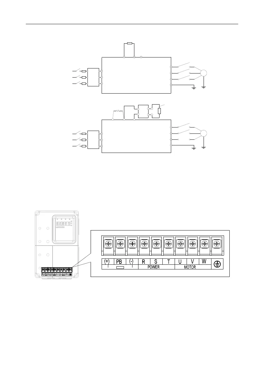
4.3.2 Connection diagram of main circuit
R
S
T
W
V
U
PE
M
Inverter of 15kW or lower
(+)
PB
3PH
380V±15%
50/60Hz
Braking resistor
Input
reactor
Input
filter
Fuse
(-)
R
S
T
W
V
U
PE
M
18.5~30kW
P1
(+)
DC reactor
(built-in)
3PH
380V±15%
50/60Hz
(-)
Input
reactor
Input
filter
Fuse
DC-
Braking resistor
DC+
Braking unit
KM1
KM1
Figure 4-8 Connection diagram of main circuit for 380V inverters
Note:
• The fuse, DC reactor, brake unit, brake resistor, input reactor, input filter, output reactor, output
filter are optional parts. Refer to Peripheral optional parts for detailed information.
• The inverters of 18.5–30kW contain built-in DC reactors.
4.3.3 Terminals in main circuit
Figure 4-9 Terminals of main circuit for the inverters of 380V 4–5.5kW
 Loading...
