Goodrive300-LIFT series inverter Installation guide
-26-
RPB U
POWER
S
T
MOTOR
V
W
(+) (-)
U-shaped short
connector between
+24V and PW
U-shaped short
connector between
COM and CME
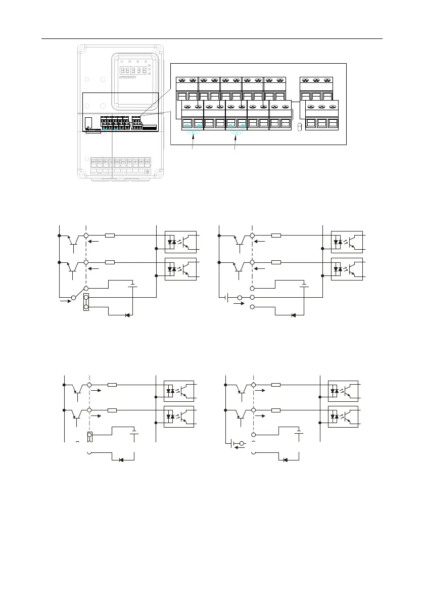
Figure 4-15 U-shaped contact tag
If the signal is from NPN transistor, please set the U-shaped contact tag between +24V and PW as
below according to the used power supply.
S1
S2
COM
PW
+ 24V
COM
+ 24V
Internal power supply (NPN mode)
S1
S2
COM
PW
+ 24V
COM
+24V
+ 24V
External power supply (NPN mode)
Figure 4-16 NPN modes
If the signal is from PNP transistor, please set the U-shaped contact tag as below according to the
used power supply.
S1
S2
COM
PW
+ 24V
COM
+24V
S1
S2
COM
PW
+ 24V
COM
+24V
Internal power supply (PNP mode) External power supply (PNP mode)
Figure 4-17 PNP modes
4.4 Wiring protection
4.4.1 Protecting the inverter and input power cable in short-circuit situations
Protect the inverter and input power cable against thermal overload in short circuit situations.
Arrange the protection according to the following guidelines.
Internal power supply (PNP mode)
External power supply (PNP mode)
 Loading...
