Goodrive300-LIFT series inverter Installation guide
-23-
grounding conductor in the motor cable in addition to the conductive shield, connect the
grounding conductor to the grounding terminal at the inverter and motor ends.
• Brake resistor, brake unit, and DC reactor are optional parts.
• Route the motor cable, input power cable, and control cables separately.
4.3.4 Wiring of terminals in main circuit
1. Connect the ground wire of the input power cable to the ground terminal (PE) of the inverter, and
connect the 3PH input cable to the terminals R, S, and T, and fasten them up.
2. Connect the ground wire of the motor cable to the ground terminal of the inverter, and connect
the 3PH motor cable to the terminals U, V, and W, and fasten them up.
3. Connect the brake resistor and other accessories that are equipped with cables to the specified
positions.
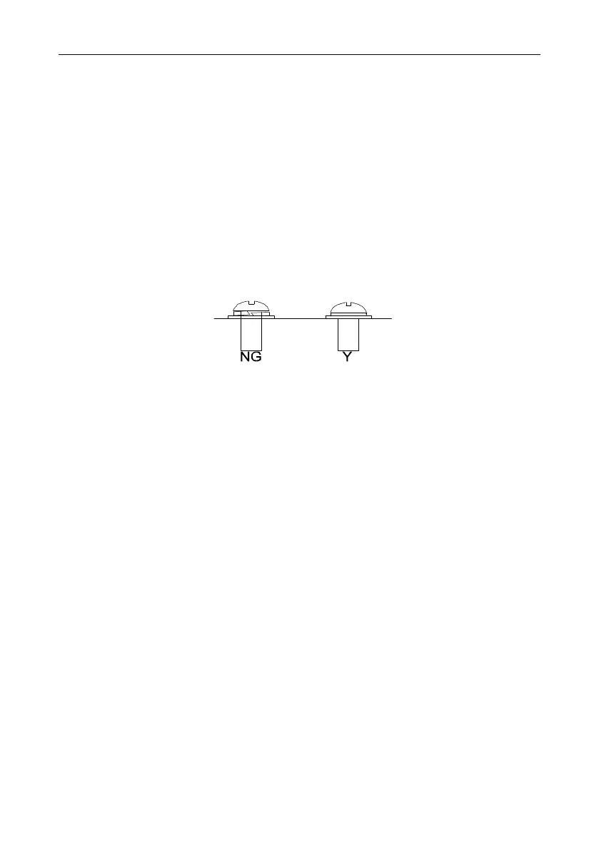
4. Fasten all the cables outside of the inverter mechanically, if possible.
Screw not fastened Screw fastened
Figure 4-12 Proper screw fastening
 Loading...
