Goodrive300-LIFT series inverter Expansion cards
-140-
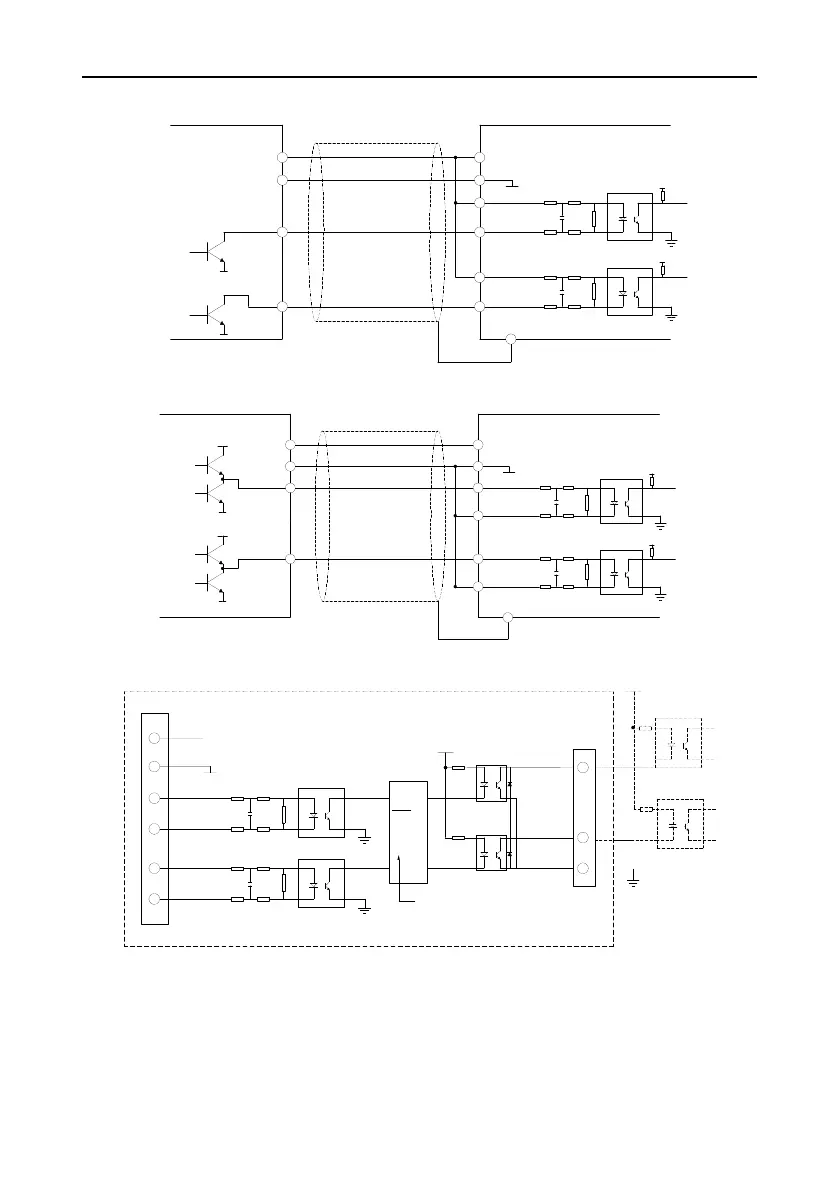
(2) Wiring diagram of open collector output encoder
TERB
-
TERB
+
TERA
-
TERA
+
+3.3V
Open collector
output encoder
Use shield cable
PG Card
B
A
+3.3V
0 V
0 V
B
A
0 V
VCC
PE
+12V
COM1
Figure A-8 Wiring diagram of open collector output encoder
(3) Wiring diagram of push-pull output encoder
TERB
-
TERB
+
TERA
-
TERA
+
A
B
VCC
VCC
0 V
+3.3V
Push-pull output
encoder
Use shield cable
PG Card
B
A
+3.3V
0 V
0 V
VCC
PE
+12V
COM1
Figure A-9 Wiring diagram of push-pull output encoder
(4) Wiring diagram of PG card frequency-division output
PG Card
COM1
TER-OB
TER-OA
Frequency-division
circuit
+12V
COM1
TERB-
TERB+
TERA-
TERA+
A
B
Figure A-10 Wiring diagram of PG card frequency-division output
A.4 Synchronous motor PG card
A.4.1 Models and specifications
The synchronous PG card is compatible with UVW encoder and SIN/COS encoder. There are two
types of model:
 Loading...
