All rights reserved. The reproduction of this document, also partially, is allowed only with authorization by alpitronic s.r.l.
2.4. Nameplate
Depending on the configuration of the charging station, the nameplate may be located on
the device.
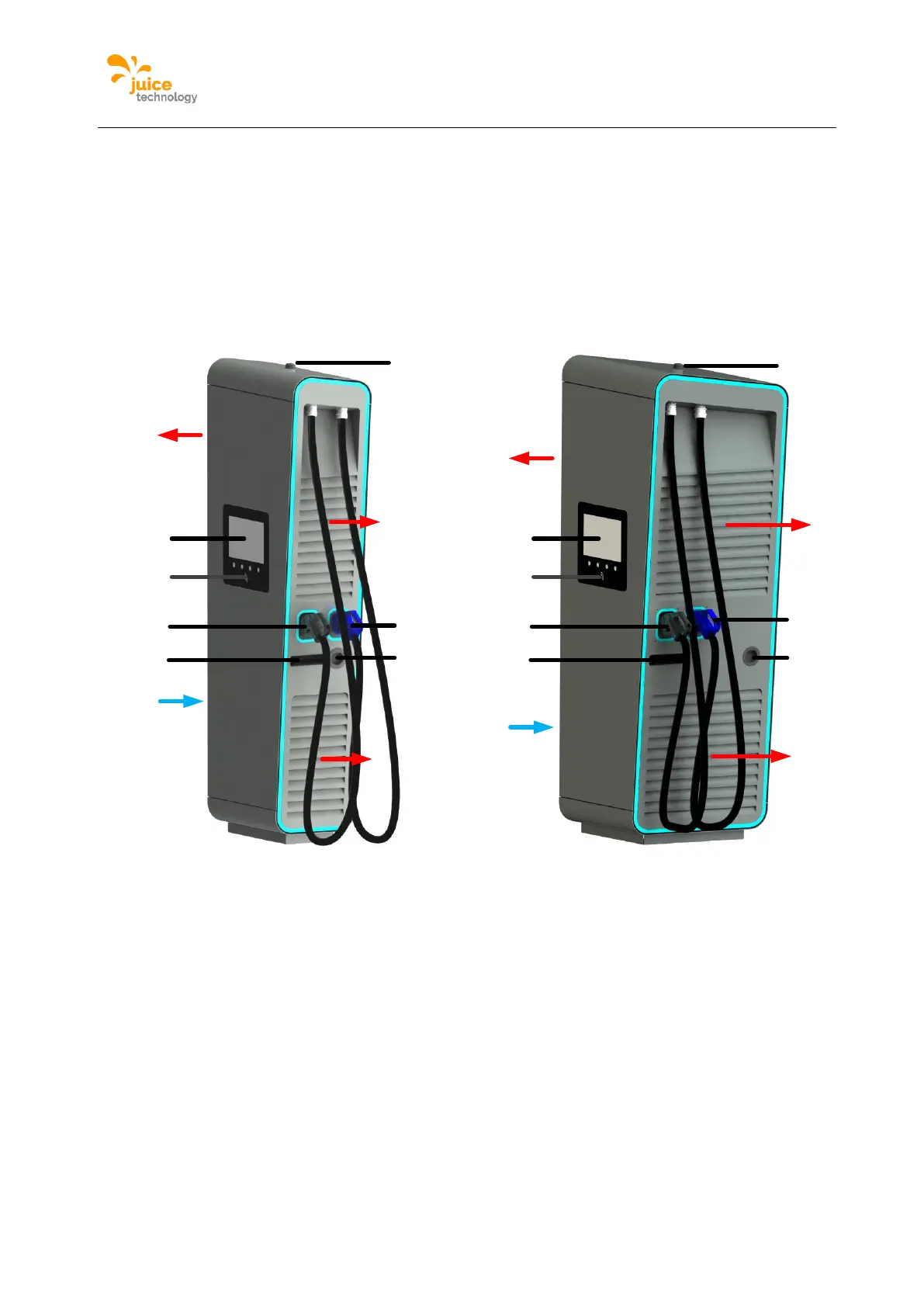
2.5. Exterior view
The following figure shows the different connections of the device from the outside.
Figure 7: Elements of the charging station
A DC charge outlet 1
B DC charge outlet 2 (optional)
C AC charge socket (optional)
D air outlet
E air inlet
G Display / HMI
H RFID card reader
I GSM / LTE antenna
J door handle
2.6. Opening of the JUICE ULTRA
The JUICE ULTRA has three doors which allow access to the inside of the device. The
service door and charging cable door are equipped with a locking cylinder to lock the device.