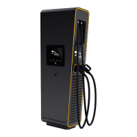
JUICE ULTRA - Operation Instructions and Installation Guide
Version 1-3A
All rights reserved. The reproduction of this document, also partially, is allowed only with authorization by alpitronic s.r.l.
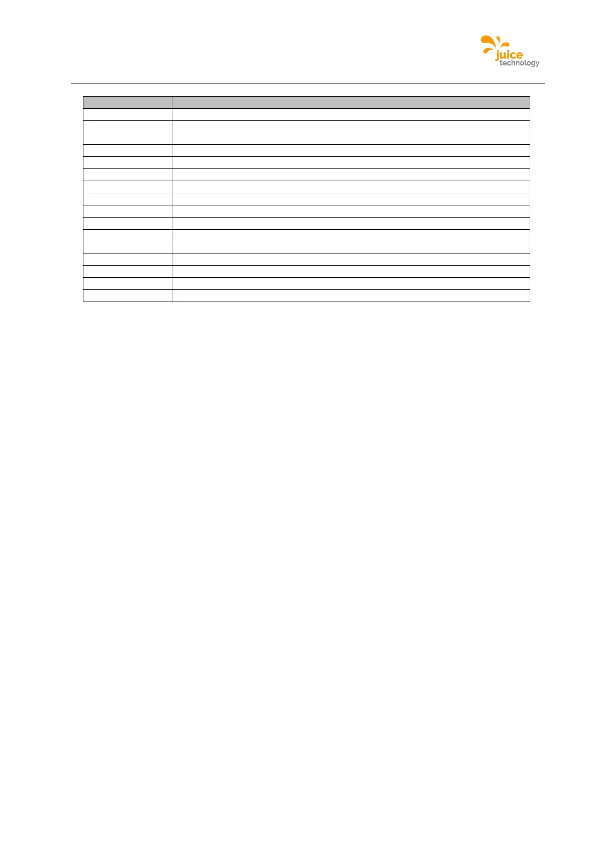
Contactors for DC charging
Contactors for AC charging (optional, only when AC-socket is present)
Auxiliary 24V power supply
Antenna (3G, LTE or WLAN)
Power socket 230Vac for service
DC-busbar for vehicle cable connection XD5 (DC-outlet 1)
DC-busbar for vehicle cable connection XD6 (optional, only when DC-outlet 2
is present)
DC charge outlet 2 (optional)
AC socket (optional, only when AC-socket is present)
RJ45 ethernet network-socket
Table 3: JUICE ULTRA double slot version cabinet components