JUICE ULTRA - Operation Instructions and Installation Guide
Version 1-3A
All rights reserved. The reproduction of this document, also partially, is allowed only with authorization by alpitronic s.r.l.
Lightning protection and EMI filter device
32A circuit breaker with fault current monitoring AC charging / 4P
16A circuit breaker with fault current monitoring for auxiliary 230Vac / 4P
125A circuit breaker / 3P / 16kA
Auxiliary 24V power supply
RJ45 ethernet network socket
Table 5: AC input switchgear components for JUICE ULTRA double slot version
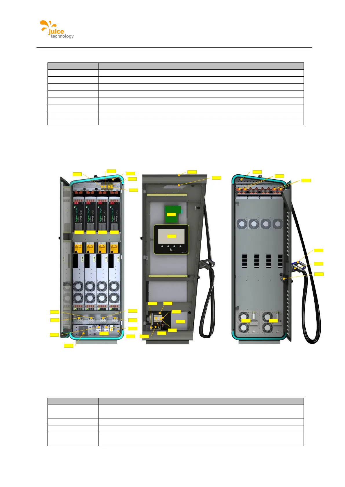
2.7.2. quadruple slot version internal view
The following figure shows the JUICE ULTRA internal view for the quadruple slot version:
Figure 14: Internal view JUICE ULTRA quadruple slot version (service-, display- and charging-cable-
side)
The following table describes the single components highlighted in the figures above:
DC fault current monitoring for AC charging (optional, only when AC-socket is
present)
DC-outlet 1 isolation monitoring device
DC-outlet 1 isolation monitoring device (optional, only when DC-outlet 2 is
present)
-TB1
-XD1
-XD6
-XD7
-XD5
-XD3
-XD4
-KF3
-KF1
-KF2
-EP1
-SF3
-TF1
-QB1
-FB2
-QA4
-BX1.1
-QA1
-FB1
-BX2.1
-TB2
-TB3
-BX2.2
-BX1.2
-QB1
-XD2
-SF2
-QA2
-QA3
-TB4
-TB5
-XF1
-EP1
-BE3
-QB7
-EP1
-BC1