JUICE ULTRA - Operation Instructions and Installation Guide
Version 1-3A
All rights reserved. The reproduction of this document, also partially, is allowed only with authorization by alpitronic s.r.l.
The following table describes the single components highlighted in the table above:
DC fault current monitoring for AC charging (optional, only when AC-socket is
present)
DC-meter for DC-outlet 2 (optional)
DC-outlet 1 isolation monitoring device
DC-outlet 1 isolation monitoring device (optional, only when DC-outlet 2 is
present)
DC-outlet 2 contactors (optional, only when DC-outlet 2 is present)
Contactors for AC charging (optional, only when AC-socket is present)
DC-busbar + pole for vehicle cable connection XD5 (DC-outlet 1)
DC-busbar – pole for vehicle cable connection XD5 (DC-outlet 1)
DC-busbar + pole for vehicle cable connection XD6 (DC-outlet 2)
DC-busbar – pole for vehicle cable connection XD6 (DC-outlet 2)
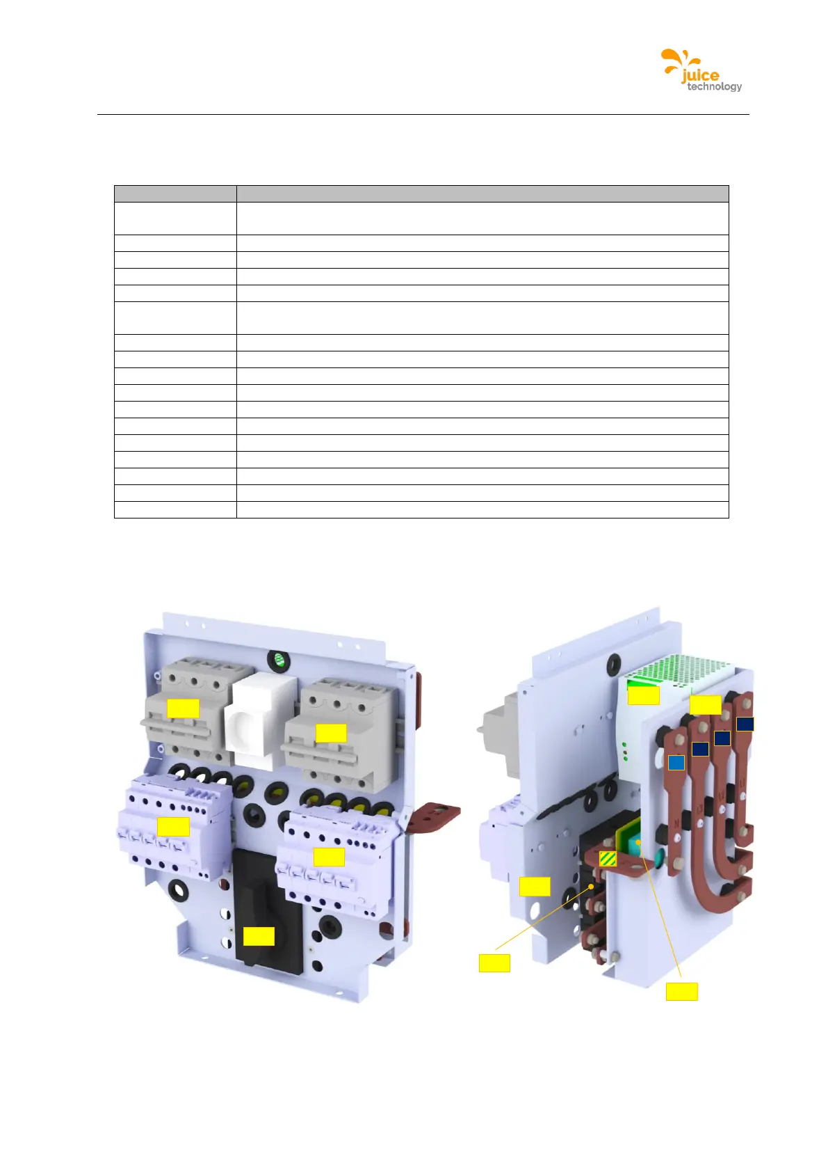
Table 4: DC output switchgear components for JUICE ULTRA double slot version
The following figure shows the AC input switchgear of the double slot version:
Figure 13: AC input switchgear of the double slot version
The following table describes the single components highlighted in the figure above:
L3
L2
L1
N
-TB1
-XD1
-FA1
-XF1
PE
-QB1
-QA1
-QA2
-FB1
-FB2
-QB1