JUICE ULTRA - Operation Instructions and Installation Guide
Version 1-3A
All rights reserved. The reproduction of this document, also partially, is allowed only with authorization by alpitronic s.r.l.
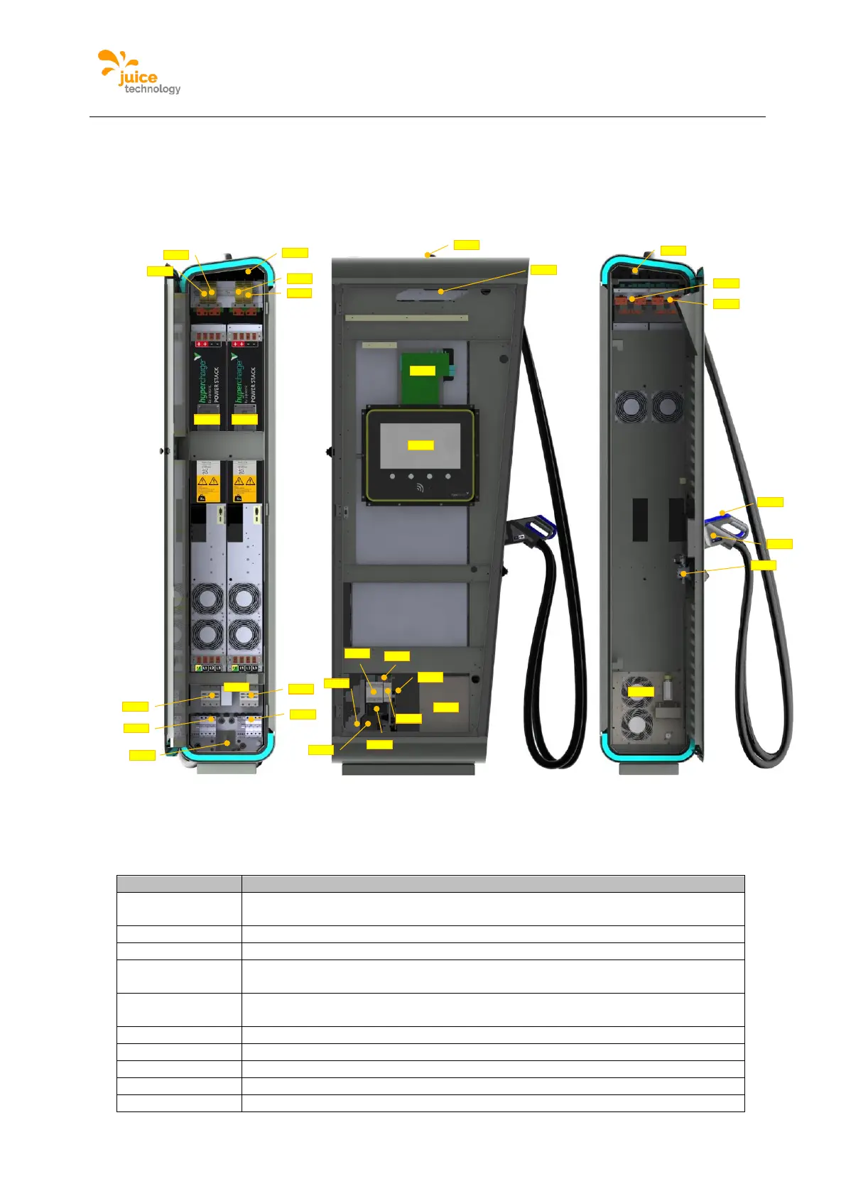
2.7. Internal view
2.7.1. double slot version internal view
The following figure shows the JUICE BOOSTER’s internal view for the double slot version.
Figure 10: Internal view JUICE ULTRA double slot version (service-, display-, charging cable - side)
The following table describes the single components highlighted in the figures above:
DC fault current monitoring for AC charging (optional, only when AC-socket is
present)
DC-outlet 1 isolation monitoring device
DC-outlet 1 isolation monitoring device (optional, only when DC-outlet 2 is
present)
Cooling unit for cooled charging cable (optional, only with cooled charging
cable)
32A circuit breaker with fault current monitoring AC charging / 4P
16A circuit breaker for auxiliary 230Vac / 4P
CTRL_COM_HD control board, CTRL_COM Display
125A circuit breaker / 3P / 16kA
-QB1
-FB2
-QA2
-BX1.1
-QA1
-FB1
-BX2.1
-TB2-TB3
-BX2.2
-BX1. 2
-QB1
-TB1
-XD1
-XD2
-XD5
-XD6
-XD7
-XD3
-XD4
-KF3
-KF1
-KF2
-EP1
-SF3
-SF2
-TF1
-EP1
-XF1
-BE 3
-QB7
-BC1