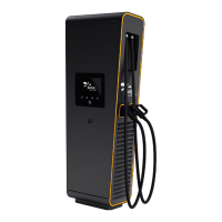
JUICE ULTRA - Operation Instructions and Installation Guide
Version 1-3A
All rights reserved. The reproduction of this document, also partially, is allowed only with authorization by alpitronic s.r.l.
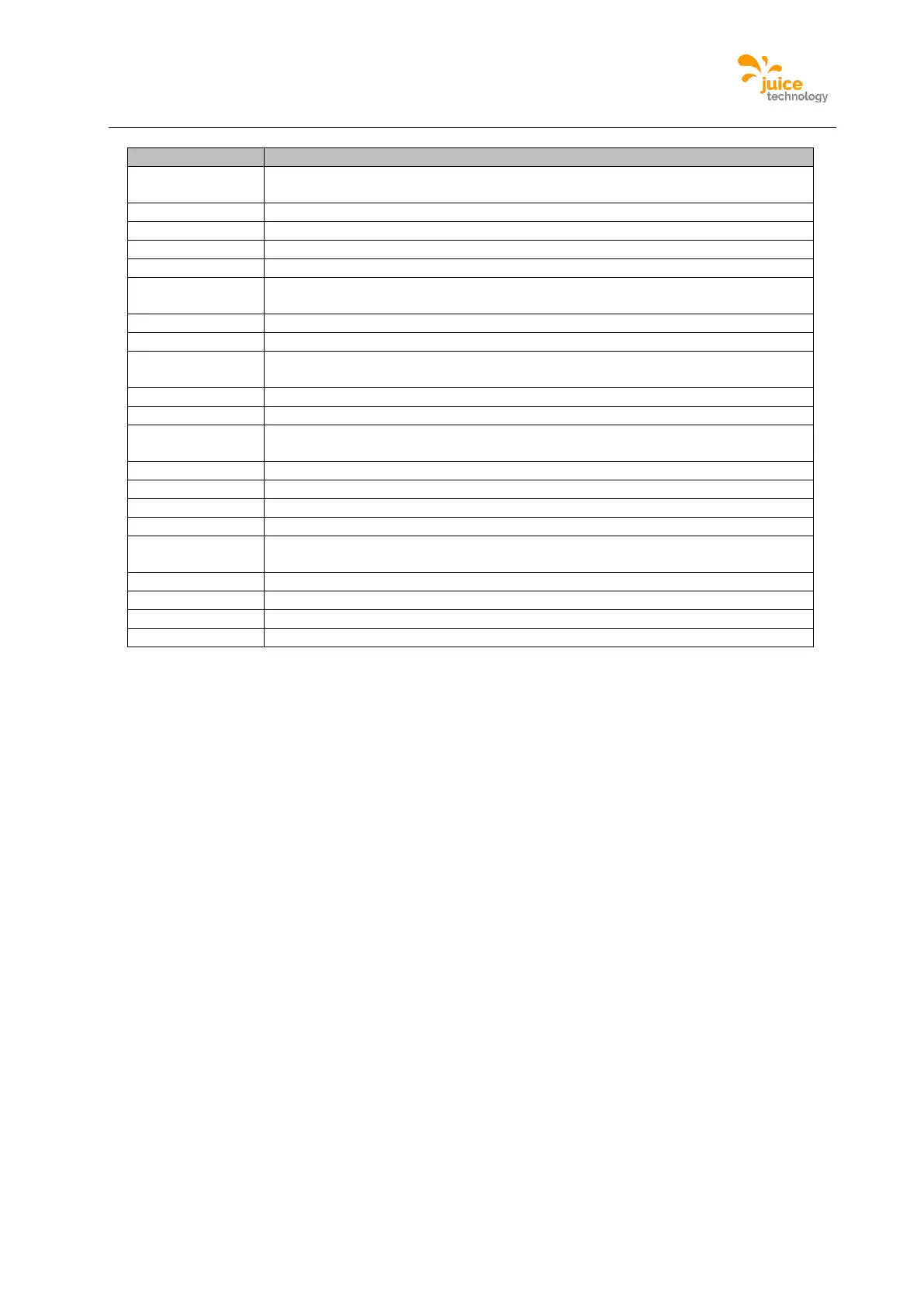
Cooling unit for cooled charging cable (optional, only with cooled charging
cable)
32A circuit breaker with fault current monitoring AC charging / 4P
16A circuit breaker for auxiliary 230Vac / 4P
CTRL_COM_HD control board, CTRL_COM Display
125A circuit breaker / 3P / 16kA
Contactors for internal DC link
Contactors for AC charging (optional, only when AC-socket is present)
Auxiliary 24V power supply
Antenna (3G, LTE or WLAN)
Power socket 230Vac for service
DC-busbar for vehicle cable connection XD5 (DC-outlet 1)
DC-busbar for vehicle cable connection XD6 (optional, only when DC-outlet 2
is present)
AC socket (optional, only when AC-socket is present)
DC charge outlet 2 (optional)
Ethernet network-dose RJ45
Table 6: JUICE ULTRA quadruple slot version cabinet components