JUICE ULTRA - Operation Instructions and Installation Guide
Version 1-3A
4 JUICE ULTRA installation
All rights reserved. The reproduction of this document, also partially, is allowed only with authorization by alpitronic s.r.l.
4.2.4. Grid Connection
The JUICE ULTRA charging stations can be used in supply networks of the type TT and TN-
S.
Attention
The necessary protective measures against electric shock and other
country-specific requirements must be taken into account.
This product has been designed for environment A. Use of this product in
environment B may cause unwanted electromagnetic disturbances in
which case the user may be required to take adequate mitigation
measures.
Depending on the configuration of the JUICE ULTRA and the EMC
measures, the protective conductor current can cause protective
conductor currents up to 1A. Please take this into account when designing
the protective earthing and protective measures.
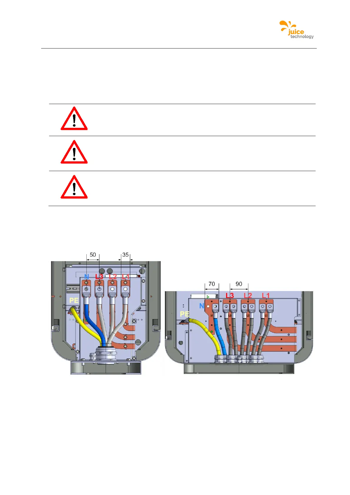
After the JUICE ULTRA is mechanically installed (Fehler! Verweisquelle konnte nicht g
efunden werden.), the main-side supply cables can be connected to the JUICE ULTRA
input Busbars:
Figure 31: Connecting of the input Busbars (double slot version left, quadruple slot version right)
The screws M12x25 should be tightening with a torque of 35Nm.