EasyManua.ls Logo

Juice ULTRA - Electrical Installation

Juice ULTRA
72 pages
Print Icon
To Next Page IconTo Next Page
To Previous Page IconTo Previous Page
Loading...
JUICE ULTRA - Operation Instructions and Installation Guide
Version 1-3A
Page 42 of 72
4 JUICE ULTRA installation
All rights reserved. The reproduction of this document, also partially, is allowed only with authorization by alpitronic s.r.l.
4.2. Electrical installation
The dimensioning of the cables and the protection devices outside the JUICE ULTRA are to
be done according the local regulations and in order to respect the technical specification of
the JUICE ULTRA stated in chapter 8.
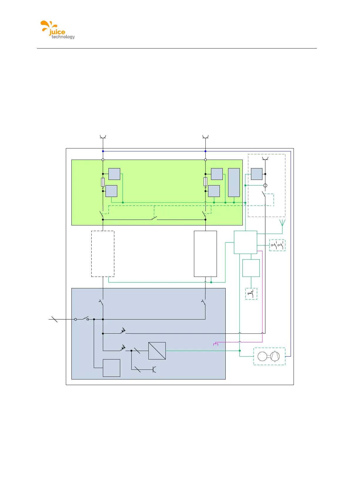
4.2.1. JUICE ULTRA schematic for the double slot version
The following figure shows the schematic of the JUICE ULTRA for the double slot version:
Figure 28: JUICE ULTRA schematic for the double slot version
DC-output
switchgear
AC input
switchgear
400V ~
24V
DC
CTRL_C
OM
Display
STACK
(AC/DC)
4
EMC,
lightning
protection
main
switch
3
DC charging
2
DC charging
1
AC-CCS
2
-FC1
2 2
4
STACK
(AC/DC)
2
GRID
-KF1
-TB1
-QB1
125A
10kA
3
125A
10kA
3
-QA2 -QA1
-FB1
-FB2
30mA/16A
10kA
4
30mA/32A
10kA
4
-FA1
-TB3
-QB3 -QB2
-QB4
-QB9
-BX2
-BX1
<R <R
-FC1
-XD1
3+N+PE
-XD2
-XD4 -XD3
-KF3
2
2
-BE3
Wh
-BE2
Wh
I/U
-BE1
Wh
I/U
-TF1
CTRL_COM
HD
-KF2
STOP
Door contact
-XF1
Ethernet
(RJ45)
-SF2 -SF3
-SF1
Power socket
230Vac
-XD11
-XD7-XD8
HYC
-BC1
DI<6mA
CTRL
_IO_1
AC-
Charging
(optional)
(option)
(option)
-EP1
(option)
Cooling unit
M
M
-TB2

Table of Contents

Related product manuals