All rights reserved. The reproduction of this document, also partially, is allowed only with authorization by alpitronic s.r.l.
8. Technical specifications................................................................................................. 69
9. Declaration of Conformity .............................................................................................. 70
List of figures
Figure 1: double slot version with one (left) and two (right) power-stacks ..........................11
Figure 2: double slot version with two DC charging cables and one AC socket .................11
Figure 3: quadruple slot version with one, two, three and four power-stacks .....................12
Figure 4: quadruple slot version with four DC charging cables and one AC socket ...........12
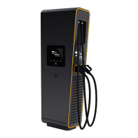
Figure 5: Standard JUICE ULTRA and barrier-free version ...............................................13
Figure 6: DC-Power characteristic with one, two, three and four JUICE ULTRA power-stacks
and different cable types ...................................................................................................14
Figure 7: Example of nameplate for JUICE ULTRA .............................................................
Figure 8: Elements of the charging station ........................................................................16
Figure 9: Order for opening the JUICE ULTRA doors .......................................................18
Figure 10: Locking mechanism for the display door ..........................................................19
Figure 11: Internal view JUICE ULTRA double slot version (service-, display-, charging cable
- side) ...............................................................................................................................20
Figure 12: DC output switchgear of the double slot version (bottom view) ........................22
Figure 13: DC output switchgear of the double slot version (top view) ..............................22
Figure 14: AC input switchgear of the double slot version .................................................23
Figure 15: Internal view JUICE ULTRA quadruple slot version (service-, display- and
charging-cable-side) .........................................................................................................24
Figure 16: DC output switchgear of the quadruple slot version (bottom view) ...................26
Figure 17: DC output switchgear of the quadruple slot version (top view) .........................26
Figure 18: AC input switchgear of the quadruple slot version ............................................27
Figure 19: Vertical transport with pallet truck or forklift ......................................................30
Figure 20: Crane eyelets on top of the packaging .............................................................30
Figure 21: Unpacking the JUICE ULTRA ..........................................................................32
Figure 22: Relevant components for the mechanical installation of the JUICE ULTRA .....34
Figure 23: Cable reach for the two DC outlets of the JUICE ULTRA .................................35
Figure 24: Recommended distances for site configuration ................................................37
Figure 25: Distances between base plate and outer dimensions of charging station on the
concrete foundation double slot version (display/top view) ................................................38
Figure 26: Distances between base plate and outer dimensions of charging station on the
concrete foundation quadruple slot version (display/top view) ...........................................39
Figure 27: JUICE ULTRA-base for the double slot version................................................40
Figure 28: JUICE ULTRA-base for the quadruple slot version ..........................................40
Figure 29: JUICE ULTRA schematic for the double slot version .......................................42
Figure 30: JUICE ULTRA schematic for the quadruple slot version ..................................43
Figure 31: Cable inlet and connection lengths for double slot version and quadruple slot
version ..............................................................................................................................44
Figure 32: Connecting of the input Busbars (double slot version left, quadruple slot version
right) .................................................................................................................................45
Figure 33: Sideview of the input Busbars (double slot version left, quadruple slot version
right) .................................................................................................................................46
Figure 34: Credentials form shown at first connection with web interface..........................48
Figure 35: Home screen of web interface ..........................................................................49
Figure 36: Example of SIM Signal webpage .....................................................................51
Figure 37: Example of Process View webpage .................................................................52
Figure 38: Example of Stop Button webpage ....................................................................53
Figure 39: Example of connector cycles webpage ............................................................53