Table 4: Chassis Status LEDs in EX2300 Switches Except the EX2300-24MP and EX2300-48MP
Models
(Connued)
LED Label Color State and Descripon
MST Green In a standalone EX2300 switch:
• On steadily—The switch is funconing normally
as the primary.
• O—The switch is powered o or is halted.
In a Virtual Chassis conguraon:
• On steadily—The switch is funconing normally
and is the primary in the Virtual Chassis
conguraon.
•
Blinking—The switch is funconing normally and
is the backup in the Virtual Chassis
conguraon.
•
O—The switch is a linecard member in the
Virtual Chassis conguraon or is halted.
A major alarm (red) indicates a crical error condion that requires immediate acon.
A minor alarm (yellow) indicates a noncrical condion that requires monitoring or maintenance. A
minor alarm that is le unchecked might cause interrupon in service or performance degradaon.
All three LEDs can be lit simultaneously.
On EX2300 switches except the EX2300-24MP and EX2300-48MP models, you can view the colors of
the two LEDs remotely through the CLI by issuing the operaonal mode command show chassis led.
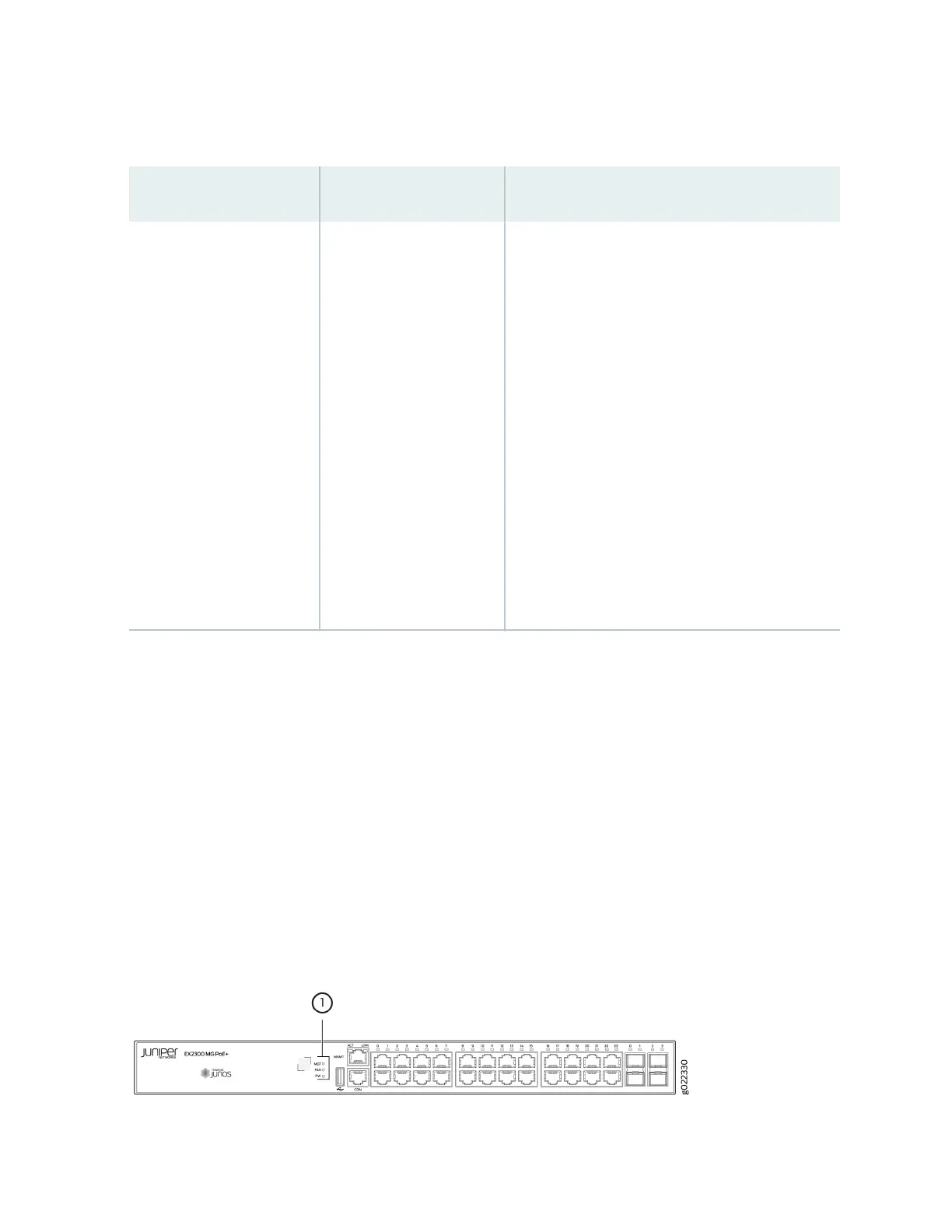
The front panel of EX2300-24MP and EX2300-48MP models has three system LEDs labeled MGT, FAN,
and PW. See Figure 18 on page 28 and Figure 19 on page 29.
Figure 18: System LEDs in EX2300-24MP Models
28
 Loading...


