EasyManuals Logo

Juniper EX2300 Series Hardware Guide

Juniper EX2300 Series
314 pages
To Next Page IconTo Next Page
To Previous Page IconTo Previous Page
Page #47 background imageLoading...
Page #47 background image
Table 12: Status LED on the Uplink Ports in EX2300 Switches Except the EX2300-24MP and
EX2300-48MP Models
LED State and Descripon
Status LED Indicates the speed and administrave status. The indicators are:
On steadily—10 Gbps
Blinking—1 Gbps
Unlit—The port is administravely disabled or the link is down.
On EX2300 switches except the EX2300-24MP and EX2300-48MP models, you can tell which port
parameter is indicated by the Status LED on RJ-45 network ports and uplink ports by issuing the
operaonal mode command show chassis led.
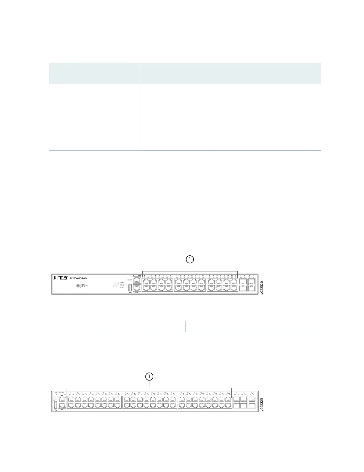
Each RJ-45 network port and uplink port on the front panel of EX2300-24MP and EX2300-48MP
switch models has one LED that indicates link/acvity. See Figure 28 on page 38, Figure 29 on page
38, Figure 30 on page 39, and Figure 31 on page 39.
Figure 28: LED on RJ-45 Network Ports in EX2300-24MP Switches
1
LED on RJ-45 ports
Figure 29: LED on RJ-45 Network Ports in EX2300-48MP Switches
38

Table of Contents

Other manuals for Juniper EX2300 Series

Questions and Answers:

Question and Answer IconNeed help?

Do you have a question about the Juniper EX2300 Series and is the answer not in the manual?

Juniper EX2300 Series Specifications

General IconGeneral
SoftwareJunos OS
ModelEX2300
Ports24 or 48 10/100/1000BASE-T ports
Uplinks4 x 1GbE/10GbE SFP+/SFP uplinks
Power SupplyInternal or external power supply options
Rack Units1U
PoE/PoE+ PortsAvailable on some models (EX2300-C and EX2300)
Operating Temperature0° to 45°C
Input Voltage100 to 240 VAC
Layer 3 FeaturesRIP, OSPF, VRRP
Layer 2 FeaturesVLAN, STP, RSTP, MSTP, LACP
Security Features802.1X, DHCP snooping
ManagementCLI, Web UI, SNMP

Related product manuals