EasyManuals Logo

Juniper QFX5110 User Manual

Juniper QFX5110
222 pages
To Next Page IconTo Next Page
To Previous Page IconTo Previous Page
Page #41 background imageLoading...
Page #41 background image
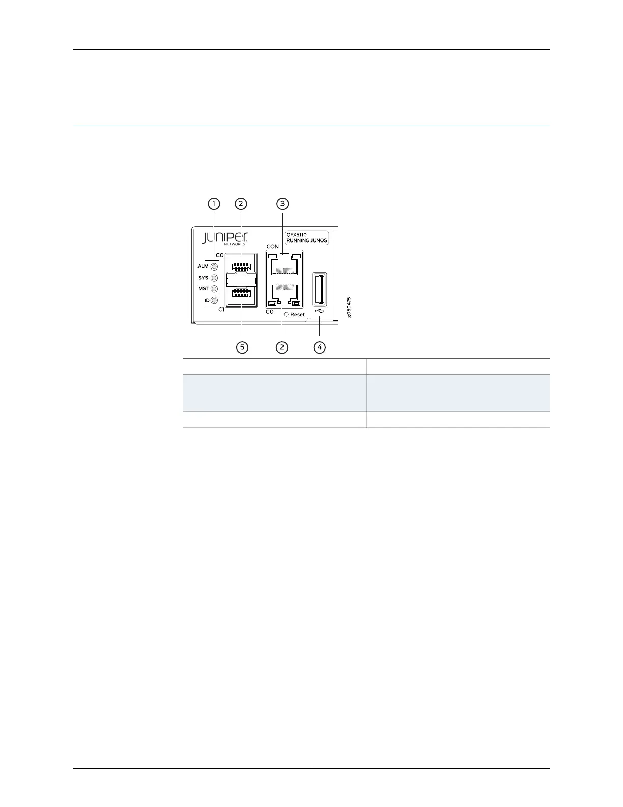
QFX5110 Chassis Status LEDs
The QFX5110 switch series has four status LEDs on the FRU side of the chassis, next to
the management ports (see Figure 8 on page 21).
Figure 8: Chassis Status LEDs on a QFX5110 Switch
4—1— USB portStatus LEDs
5—2— em1–SFP management Ethernet port (C1)
cage (socket for either 10/100/1000 BASE-T
RJ-45 SFP or 1-GbE fiber SFP)
em0–RJ-45 (10/100/1000 BASE-T)
management Ethernet port (C0)
3—RJ-45 console port (CON)
Table 11 on page 22 describes the chassis status LEDs on a QFX5110, their colors and
states, and the status they indicate. You can view the colors of the three LEDs remotely
through the CLI by issuing the operational mode command show chassis lcd.
21Copyright © 2017, Juniper Networks, Inc.
Chapter 2: Chassis Components and Descriptions

Table of Contents

Questions and Answers:

Question and Answer IconNeed help?

Do you have a question about the Juniper QFX5110 and is the answer not in the manual?

Juniper QFX5110 Specifications

General IconGeneral
ModelQFX5110
Power SupplyDual, hot-swappable
Rack Units1U
Operating Relative Humidity5% to 90% non-condensing
Input Voltage100-240 VAC
Operating SystemJunos OS
Layer SupportLayer 2 and Layer 3
Virtual Chassis SupportYes
Ports48 x 10GbE SFP+
Jumbo Frames9216 bytes
Operating Temperature32°F to 104°F (0°C to 40°C)
Operating AltitudeUp to 3, 048 m
ManagementCLI
AC Input Frequency50/60 Hz
Storage Temperature-40°C to 70°C
MTBFConsult Juniper documentation for specific values.

Related product manuals