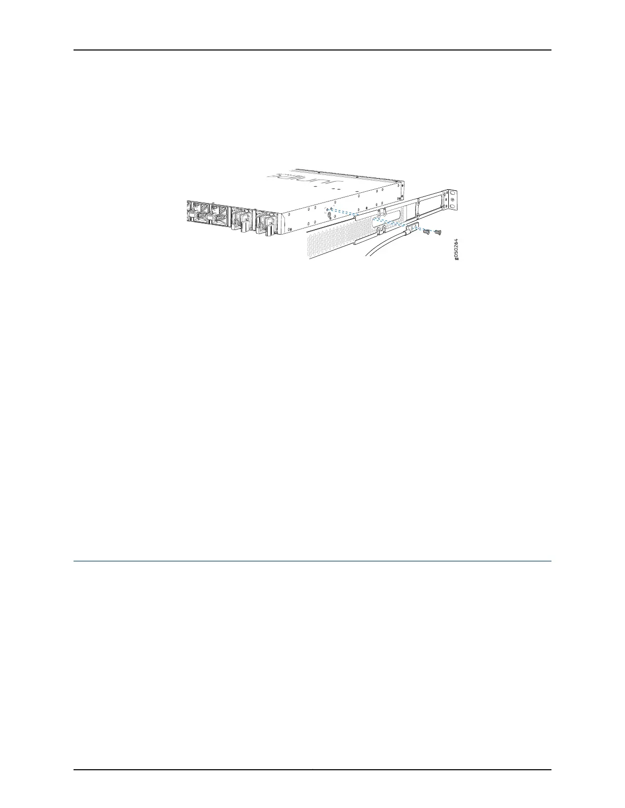
1. Secure the provided protective earthing terminal bracket through the QFX5110
mounting bracket to the chassis with the #10-32 screw and washer. The posts on the
protective earthing terminal bracket should point to the left. See Figure 27 on page 85.
Figure 27: Connecting a Grounding Cable to a QFX5110
2. Connect one end of the grounding cable to a proper earth ground, such as the rack in
which the switch is mounted.
3. Place the grounding lug attached to the grounding cable over the protective earthing
terminal on the protective earthing terminal bracket.
4. Secure the grounding lug to the protective earthing terminal with two screws and
washers.
5. Dress the grounding cable and ensure that it does not touch or block access to other
device components and that it does not drape where people could trip over it.
Related
Documentation
General Safety Guidelines and Warnings on page 153•
• Grounded Equipment Warning on page 168
• Connecting AC Power to a QFX5110 on page 85
• Connecting DC Power to a QFX5110 on page 87
Connecting AC Power to a QFX5110
The QFX5110 is shipped with two650 W power supplies pre-installed. Each power supply
is a hot-removable and hot-insertable field-replaceable unit (FRU) when the second
power supply is installed and running. You can install replacement power supplies in the
two slots next to the fan modules without powering off the switch or disrupting switch
functions.
Ensure that you have a power cord appropriate for your geographical location available
to connect AC power to the switch.
Before you begin connecting AC power to the switch:
•
Ensure thatyou have taken the necessaryprecautions to prevent electrostatic discharge
(ESD) damage (see “Prevention of Electrostatic Discharge Damage” on page 182).
85Copyright © 2017, Juniper Networks, Inc.
Chapter 10: Connecting the Switch to Power