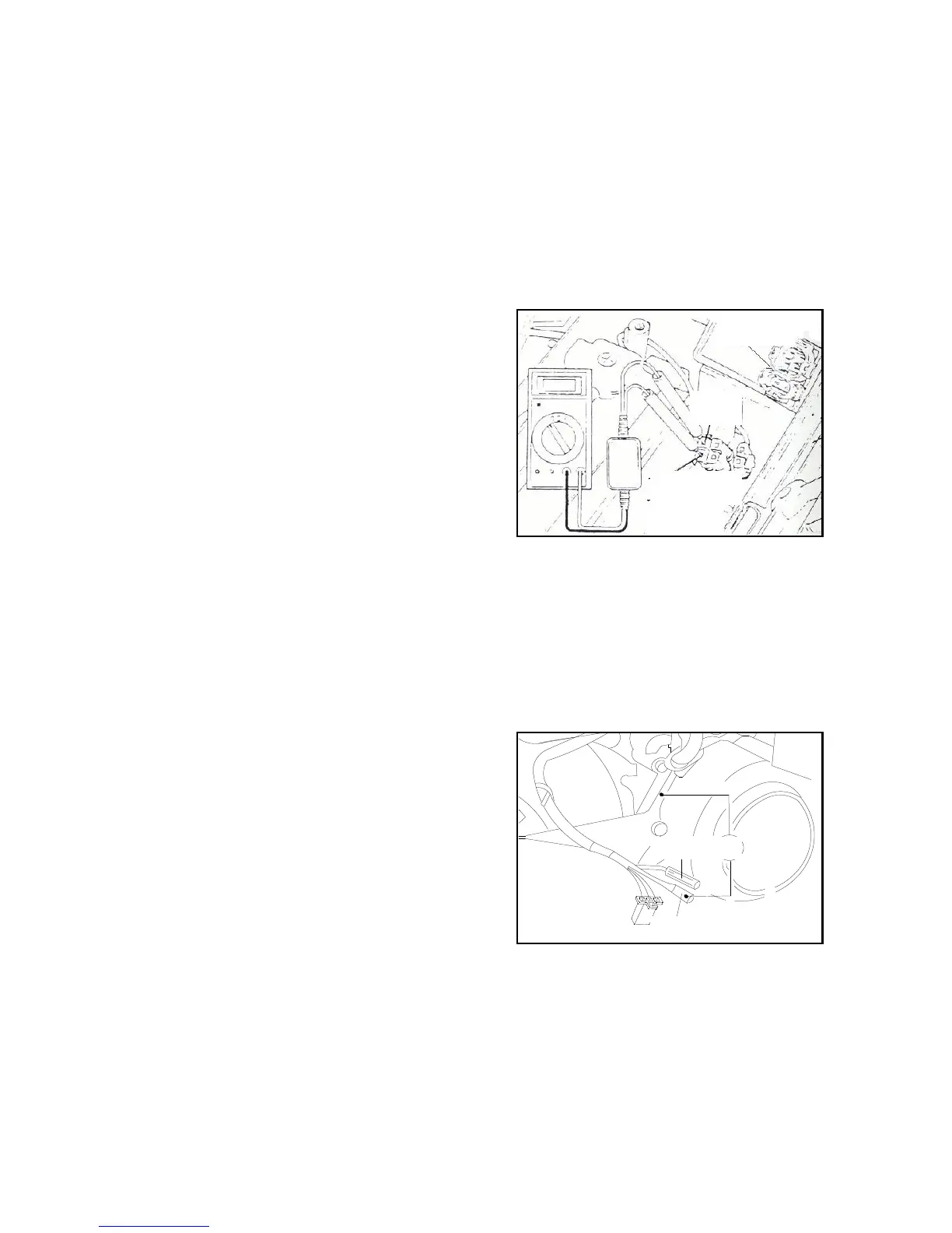
coil (black/red) and the 4P joint (black end). Start the
motor or step on the actuating lever to determine the
maximum voltage of charging coil.
Connection Method:black/red end to the positive
pole and black end to the negative pole.
Minimum Voltage:above 95V.
* Note
Never touch the metal of test prod when measuring the
voltage in case of electric shock.
Remove the adaptor of the alternator when the peak voltage
Of the adaptor of CDI group is abnormal.
Connect the charging coil (black/red) with the shunt.
• If the obtained voltage of the end of CDI group is abnormal
while the one of the end of the alternator is normal, the
problem should be poor contact or wire break.
• If both ends are abnormal, the charging coil may be broken,
please refer to the inspection method of charging coil.
2.3.3 Trigger
* Note
Install the spark plug in the cylinder head and carry out the
measuring when the compression pressure is normal.
Remove the 4p and 2P joints of CDI group, connect the
peak-voltage magnetor between the trigger with wiring 2p
end (blue / white end) and 4p end (black end). Press the
starting motor or step on the actuating lever to measuring the
peak voltage of the trigger.
Connection Method:Blue/white end to the positive pole and
black end to the negative pole.
Minimum Voltage:above 1.7V.
* Note
Never touch the metal of test prod when measuring
the voltage in case of electric shock.
Remove the adaptor of the alternator when the peak voltage
of the adaptor of CDI group is abnormal.
Connect the magnetor of and the trigger (blue/white).