2- 10 Keysight N9912-90001 User’s Guide
Preparing for Initial Use of Your New FieldFox
Take the FieldFox Tour
2-
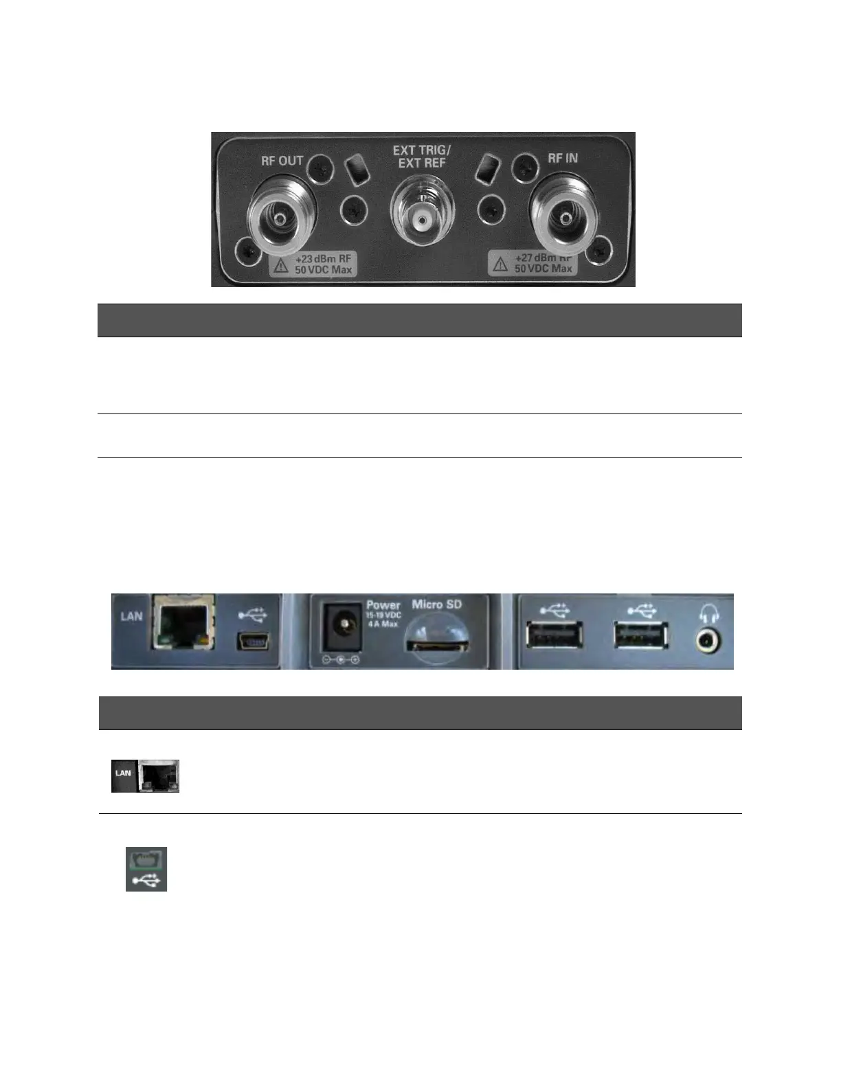
Top Panel
Side Panel
Caption Descriptions Learn More:
RF Output For CAT and NA measurements, use to make reflection measurements.
Maximum: ±50 VDC, +23 dBm RF
“CAT Mode Settings”
on page 3-3
“NA Mode Settings” on
page 5-3
Ext Trig/Ext
Ref
External Reference connector to connect to an external frequecny reference.
Maximum: 5.5 VDC.
“SA Mode Settings” on
page 8-4
RF In For CAT and NA mode, use to make transmission measurements.
For SA use to make all measurements.
Maximum: ±50 VDC, +27 dBm RF.
“Frequency Reference
Source” on page 18-15
“Triggering” on page
8-25
Connector Description Learn More
Ethernet cable connector to read trace data using the FieldFox Data Link
Software and connect to the FieldFox remotely.
Download the latest version of the software at:
www.keysight.com/find/fieldfoxsupport
On the N9912A units with serial number prefixes ≥5607, the mini-USB port
can be connected to your PC’s standard USB port to send SCPI commands.
Chapter 19, “Using
the Mini-USB Port
to send SCPI
Commands and
Queries (N9912A
units with serial
number prefixes
≥5607 Only)”, on
page 19-1