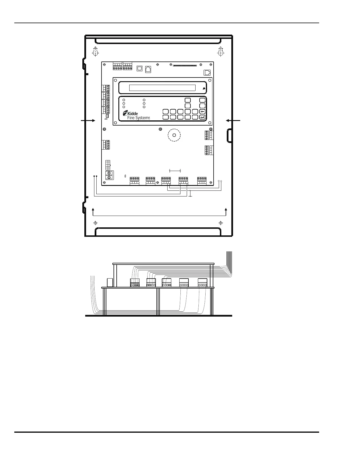
Figure E-1. Power-Limited and Non-Power-Limited Wiring
Combo 2
TB6TB7
Combo 1
TB2
Aux 24 VDC
TB11
Release 2
TB12
Release 1
Batt Out
TB3
TroubleRelay 3Relay 1 Relay 2
1234 1234
1234
12 34 1 2 34
120
240
TB13
AC IN
NL
PSU
J12
+
+
--
CNCNO
CNCNO
CNCNOCNCNO
1234
TB5
NAC 1
TB14
1234
NAC 2
RS-232 A
J8
J5
TB15
USB B
RS 485SLC
TB1
4321 4321
Style 4
S2
J10
J3
RS-232 B
TB4 TB8 TB9 TB10
Use left-side gutter for non-
power-limited wiring.
Use right-side gutter for power-
limited wiring.
A-A
Maintain 1/4-in. separation as shown between power-
limited and non-power-limited wiring in this area.
1/4-in. (min.)
1/4-in. (min.)
Non-power-limited wiring
Power-limited wiring
Note:
Route wiring as shown when combination power-limited and non-power-limited circuits are used.
Direct all non-power-limited wiring to the rear and then to the left-hand side of the enclosure. Tie wrap this wiring to the
back of the enclosure to maintain a minimum 1/4-inch separation from all power-limited wiring.
Direct all power-limited wiring outward and then to the right-hand side of the enclosure. Also tie wrap this wiring as
necessary to maintain a minimum 1/4-inch separation from all non-power-limited wiring.
A-A
Non-power-limited
wiring
Power-limited wiring
AC POWER
ALARM
PRE-ALARM
SYSTEM TROUBLE
SUPERVISORY
SILENCE
SYSTEM
ACKNOWLEDGE
SYSTEM
RESET
SILENCE
SCROLL
12345
67890