Appendix C: Applications
P/N 3102352-EN • REV 005 • ISS 28DEC18 219
Typical wiring for zone alarm signaling
The 24 VDC riser that supplies power to the sounder bases is supervised using a FX-NAC
Analog NAC Module.
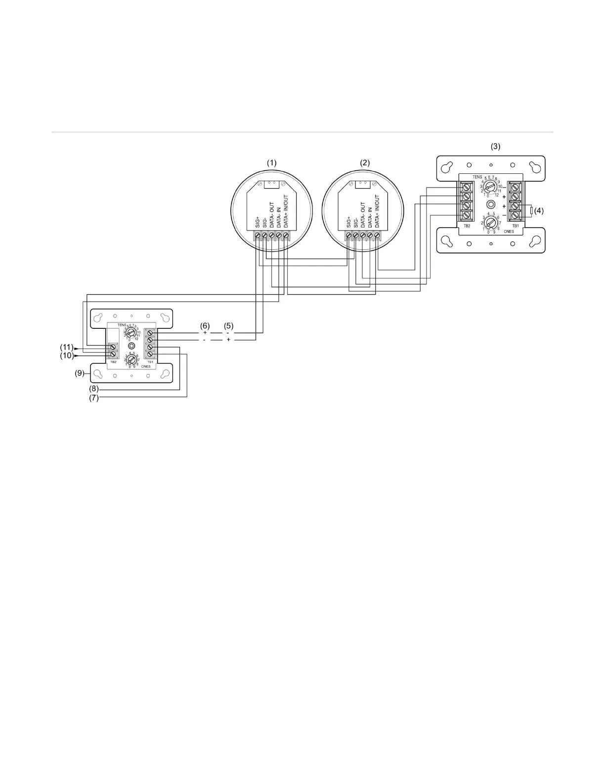
Figure 59: Typical wiring for a zone alarm signaling application
(1) First detector (sounder base)
(2)
Last detector (sounder base)
FX-NAC
47 kΩ EOLR
Active
(8) AUX riser 24 VDC +
(9) FX-RLY
(10) SLC IN −
(11) SLC IN +
Programming for zone alarm signaling
This application requires that you group your detectors into zones and correlate outputs for
each zone. The following instructions are for Zone 1 but apply for all zones as well.
Note: For PD, PHD, and PDD detectors configured as “Supervisory Non-latching” device type
or for PCD detectors (smoke element) configured as “Smoke Supervisory Non-latching” device
type, if the base is Relay/Sounder, then the follow type option cannot be configured as “Head.”
The follow type in this case should be set to “Alarm.”
To program a zone alarm signaling application:
1. Set the panel’s Event Notification option to Zone.
2. Configure the smoke detectors in Zone 1 as follows:
Device Type: Smoke or Smoke Heat depending on the detector model