Chapter 1: Installation and wiring
18 P/N 3102352-EN • REV 005 • ISS 28DEC18
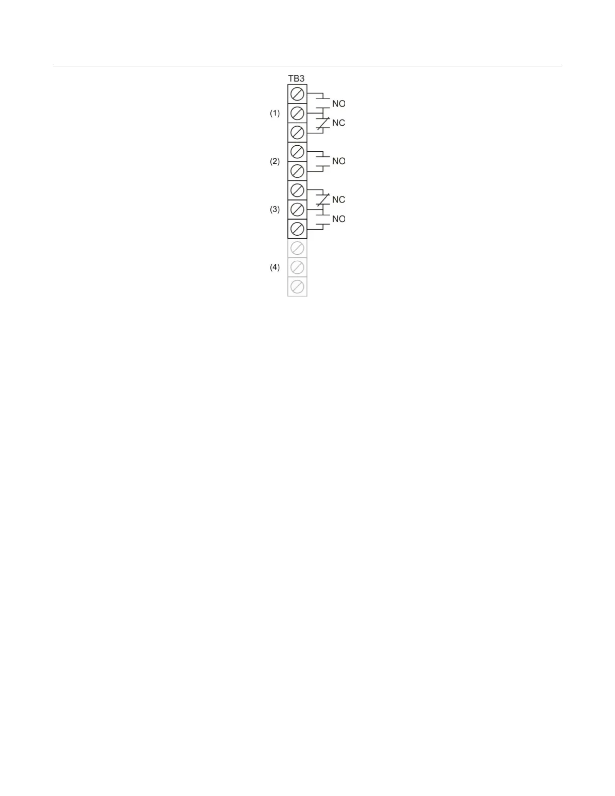
Figure 22: Relay wiring terminals
(1) Common trouble relay
(2) Common supervisory relay
(3) Common alarm relay
(4) Auxiliary/Smoke power output
Note: The figure above shows the panel in a normal state.
Remote annunciator wiring (TB4)
The control panel provides a connection for up to eight remote annunciators.
Circuit specifications
• Class B or Class A
Note: The FX-64 panel requires the SA-CLA card to support Class A and redundant Class
B circuits. Refer to “SA-CLA wiring” on page 26, or to installation sheet P/N 3101094-EN.
• Circuit voltage: 2.55 V peak-to-peak average
• Circuit current: 30 mA max.
• Circuit resistance: 90 Ω
• Circuit capacitance: 0.3 µF
• Ground fault impedance: 0 to 5 kΩ
• RS-485 communications speed: 9600 baud
• Wiring: 18 to 14 AWG (1.0 to 2.5 mm
2
) twisted pair
• Wire run: 4,000 feet (1,219 m) max.
• Power-limited and supervised