3.1 Specification for ECOTRONIC
The Ecotronic system control unit is a decentralised microprocessor
system (CAN BUS). To control the boiler system, the Ecotronic com-
prises a module (PCB) integrated into the control panel, and the pro-
gramming module. Controller modules can be added to the Ecotronic
(modular structure). It is therefore possible to extend operation indi-
vidually according to customer requirements.
Structure and function
Modular structure
The Ecotronic system control unit is a decentralised microprocessor
system (CAN BUS). To control the boiler system, the Ecotronic com-
prises a module (PCB) integrated into the boiler, and the programming
module. Three-sensor cylinder management is part of the standard
Ecotronic version. Controller modules can be added to the Ecotronic
(modular structure). It is therefore possible to extend operation indi-
vidually according to customer requirements.
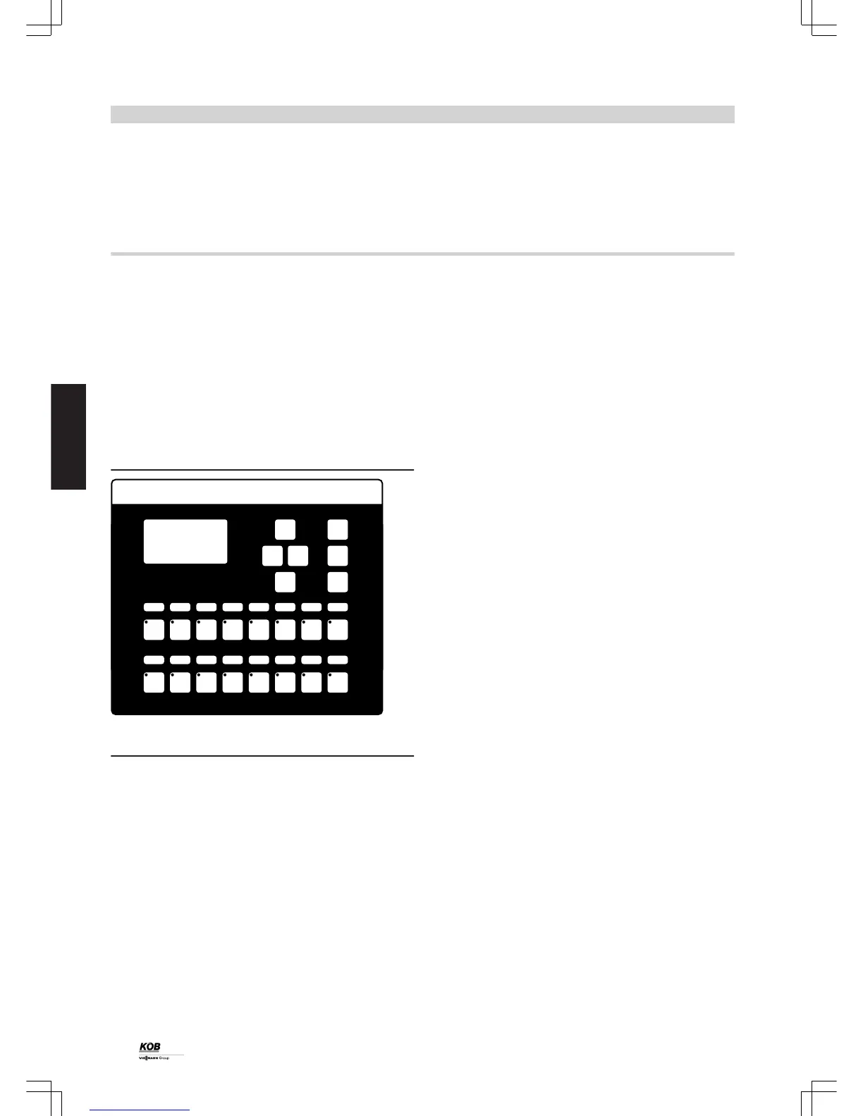
Programming module
The programming module is included in the standard delivery for the
boiler and is used to operate the heating system. The backlit screen
offers an extensive text display. A data cable connects the program-
ming module with the control panel.
The programming module
Functions:
■ Automatic ignition
■ Output control circuit with modulating output operation (25-100 %)
– Air-controlled by means of variable speed flue gas fan subject to
flow temperature
– Exact fuel supply via the supply screw conveyor from dosing con-
tainer with separating barrier
– Topping up of the dosing container with level monitoring
– Limitation and distribution of the mass to be burned in the com-
bustion chamber by means of level monitoring in the combustion
chamber and movement of the infeed grate.
■ Emission optimised control circuit: Optimisation of the air supply
through motorised air dampers using Lambda probe measurement
ensures optimum combustion
■ Keeping up the return temperature with the boiler mixer ensures a
long boiler service life
■ Control unit for oil burner on the PYROT
■ Safety functions for:
– Excessive temperature
– Burn-back
– Opening of a charging cover
– Forced heat transfer
■ Potential-free output (fault message)
Operation:
Operation is carried out via a control panel with touch-sensitive keypad
and plain text display. All operating data can be shown on the display.
The set values of all important parameters can be entered easily with
a keyboard. Fault messages are displayed in plain text and output in
the sequence of occurrence.
Standard delivery:
■ Microprocessor control unit (control panel with backlit plain text dis-
play), CE-tested, real time clock, battery backed, serial interface RS
232 for PC connection
■ Data cable from the programming module to the control panel; length
10 m
■ Control panel, surface powder-coated in RAL 7035 (grey) texture.
Version, as per ÖVE/VDE directives, fully wired to terminal strips,
feed 3 x 400 V 50 Hz; control voltage 230 V or 24 V;
– Update-compatible software
– Starttec for all charging drives (3 x 400 V) according to separate
price items
– Motor overload relay for boiler pump
– Outputs for stepper motors (air dampers)
– Inverter (EMC operating class 3) for flue gas fan
■ In the control panel door:
– 4-pole main isolator
– Documentation incl. fixed wiring diagram, terminal connection dia-
gram with cable designation, operating and maintenance instruc-
tions, installation instructions in plan pocket
■ Sensors and switches installed at the supply screw conveyor:
– Infrared light barrier, level monitoring, separating barrier, supply
screw conveyor
– Safety limit switch on inspection cover of supply screw conveyor
– Contact sensor PT-100 at the supply screw conveyor
■ Sensors and switches at the combustion block, the combustion sys-
tem and in the flue outlet (installation on site):
– Infrared light barriers, level monitoring, fuel in combustion cham-
ber
– Zirconium dioxide probe with measured value transducer (Lambda
probe)
– Flue gas temperature sensor PT-100
■ Sensors and switches installed at top of boiler:
– Boiler water temperature sensor KTY in connector flow
– Return temperature sensor KTY in connector return
– High limit safety cut-out (STB)
– Temperature sensor, rotary fan
■ Sensor supplied
– 1 sensor KTY with sensor well 1/2 " x 280 mm (B28.1)
Control unit
14
PYROT
3
5822 516 GB