2.2 Specification
Specification
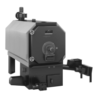
Trade name Pyrot rotation combustion
Rated output kW 100 150 220 300 400 540
Part no.: 7423 656 7423 657 7423 658 7423 659 7423 660 7423 661
Output data
Rated output kW 100 150 220 300 400 540
Continuous output
*1
kW 90 135 200 270 360 480
Minimum output Q
min
*2
kW 30 45 60 80 100 140
Heating data
– Content on hot gas side l 325 374 744 883 1340 1613
– Permissible shutdown temperature of
the high limit safety cut-out.
°C 100 100 100 100 100 100
– Minimum return temperature °C 65 65 65 65 65 65
– Grate ash container capacity l 26 32 45 55 75 91
– Ash container capacity, flue gas dust
extractor
l 90 90 90 90 90 90
Boiler water content l 395 432 794 903 1326 1510
Pressure drop on the DHW side mbar 38 33 76 42 29 56
Permiss. operating pressure
Test pressure bar 5 5 5 5 5 5
Maximum operating pressure bar 3 3 3 3 3 3
Heating surface
m
2
8.28 10.78 16.4 20.72 28.76 39.36
CE designation CE CE CE CE CE CE
Boiler class to DIN EN 303-5 3 3 3 3 3 3
Overall dimensions
Total length (with door open) mm 2870 3120 3424 3780 4004 4232
Total width mm 1050 1050 1330 1330 1570 1570
Total width (with supply screw conveyor) mm 2070 2180 2350 2350 2590 2590
Total height mm 1825 1825 2084 2084 2422 2492
Total height (with induced draught fan) mm 2236 2266 2526 2534 2832 2902
Total weight
–
Boiler
*3
kg 1278 1451 2119 2441 3235 3671
– Combustion block kg 432 477 581 641 778 937
– Displacer rods kg 68 87 141 163 220 289
– Flue gas fan kg 37 40 40 45 62 62
– Supply screw conveyor kg 143 143 143 143 143 149
–
Total dry weight
*4
kg 1958 2198 3024 3433 4438 5108
– Total wet weight kg 2353 2630 3818 4336 5764 6618
Max. power consumption
– During ignition W 1600 1600 1600 1600 1600 1600
– Electrical connections (total) W 2670 2670 2850 3600 3980 3630
– Supply screw conveyor W 370 370 550 1100 1100 750
– Rotary fan W 120 120 120 120 120 120
– Flue gas fan W 550 550 550 750 1100 1100
– Grate drive W 30 30 30 30 60 60
– Electrical power consumption with Q
N
W 850 1032 1108 1521 1868 1753
– Electrical power consumption with Q
min
W 280 355 369 434 480 460
Boiler connections
Boiler flow and return G 2 fem. 2 fem. DN80 PN6 DN80 PN6 DN100 PN6 DN100 PN6
Extinguishing water connection R ¾ ¾ ¾ ¾ ¾ ¾
Boiler drain valve Rp 1 ½ 1 ½ 1 ½ 1 ½ 1 ½ 1 ½
Safety heat exchanger 2x R ½ ½ ½ ½ ½ ½
Sensor well for TS Rp ½ ½ ½ ½ ½ ½
*1
Levelled output as base load boiler in continuous operation with pneumatic cleaning
*2
Q
≥
Q
min
: Output operation modulating control (variable output control)
Q
≤
Q
min
: Low load with ON Q
min
/ OFF (Stop and Go operation)
*3
Incl. door and refractory concrete lining
*4
Incl. displacer rods
PYROT rotation combustion
(cont.)
PYROT
9
5822 516 GB
2