Ash removal into the base container
Complete screw conveyor ash removal from the combustion block ash
chamber into the base container located under the boiler with maxi-
mum capacity. The light barrier control unit keeps the ash level via the
screw conveyor constant. In this way, the ash can transfer all its heat
in the ash trough under the combustion system and only cooled ash is
fed into the container in normal operation. The large base container
ensures maximum maintenance free intervals.
Standard delivery:
■ Boiler ash trough with ash level control and ash removal screw con-
veyor made from heat-resistant steel; driven via a geared screw
conveyor motor
■ Base container with a maximum capacity and two maintenance
doors for the removal of ash by means of a vacuum cleaner or stok-
ing device
■ Control of ash removal with light barrier
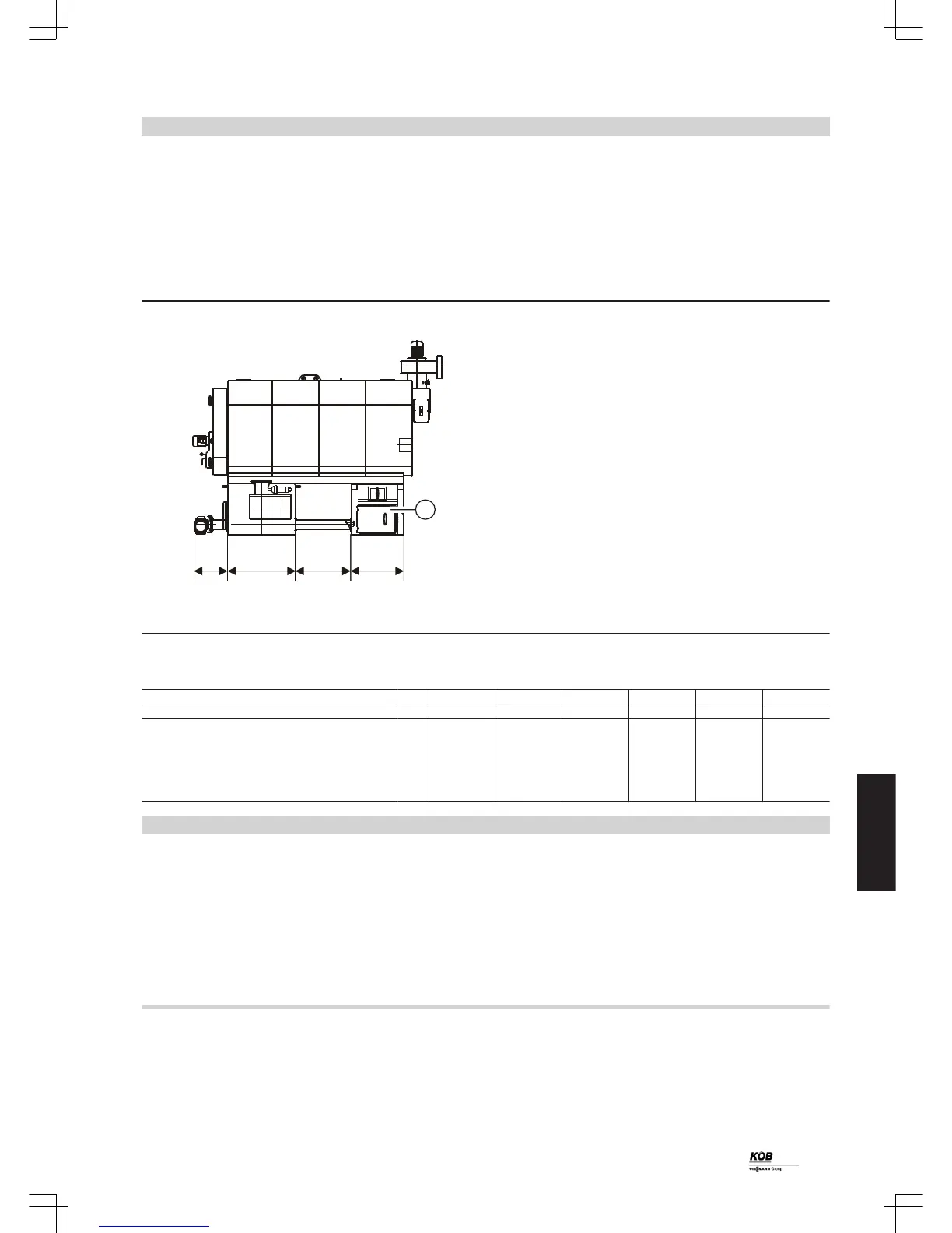
A
Boiler ash trough door
Dimensions
Rated output kW 100 150 220 300 400 540
Part no.: 7387 911 7388 031 7387 789 7387 835 7388 029 7388 021
Dimensions
a mm 640 740 740 880 960 1096
b mm 448 450 513 787 456 551
c mm 593 593 680 680 800 800
Volume of base container l 220 240 360 380 600 700
Additional weight to the boiler kg 300 320 340 360 380 400
Design information
6.1 System design
Selection of rated output
Select the wood boiler according to the required heat load. The Pyrot
should be planned as a base load boiler and always operated in con-
junction with a buffer cylinder (management). The correct system
design point therefore does not depend on the nominal load specifi-
cation (i.e. the building heat load) but rather on the required duration
of use (length of the heating period, heat demand).
Note
In places more than 1800 metres above sea level, the project enquiry
must include information about the exact geographical location (alti-
tude and address of the location).
Flow temperatures
To minimise distribution losses, we recommend that you size the heat
distribution system and the DHW heating to a max. flow temperature
of 70 ºC.
For wood boilers supplied with a boiler control unit, the max. boiler
water temperature is limited to 85 ºC. The flow temperature may be
increased by adjusting the control thermostat.
Installation accessories
(cont.)
PYROT
41
5822 516 GB
6