6.21 Connection on the flue gas side
Chimney
The system is equipped with a flue gas fan and therefore the combus-
tion equipment does not require a draught. The stack sizing should be
carried out in the same way for combustion equipment with a pressure-
jet oil or gas burner without draught requirement (flue gas temperature
at rated load 160-200 °C). The PYROT rotation combustion system
has variable output control modulating between 30-100 % of rated
output. This results in flue gas temperatures in the range of
min. 100 °C and max. 250 °C. In order to avoid a risk of soot contam-
ination, there should be an insulated chimney. The route from the flue
gas fan to the chimney should be as short as possible. 90° bends
should be avoided wherever possible. Flue pipes more than 1 m long
should be thermally insulated. The chimney should be connected ris-
ing at an angle of 30- 45°. The flue pipe incl. inlet to the chimney must
be gas-tight. For the operation of the Pyrot rotation combustion in
accordance with the regulations, a draught stabiliser (draught limiter)
is required in the chimney.
A chimney compliant with regulations relevant to the rated boiler output
is required for efficient boiler operation.
Provide verification to DIN EN 13384.
Note that in its lower output range, flue gas temperatures below
90 ºC may be generated. Therefore connect the boiler to a moisture-
resistant chimney (thermal resistance class I to DIN 18160 T1).
If the boiler is not being connected to a moisture-resistant chimney,
carry out a chimney calculation or request a chimney assessment
(values for a chimney calculation, see page 10).
Flue pipe (sizing)
The induced draught fan may cause vibrations, which can lead to
excessive noise. We therefore recommend you mate the connector to
the chimney with a flexible flue pipe adaptor.
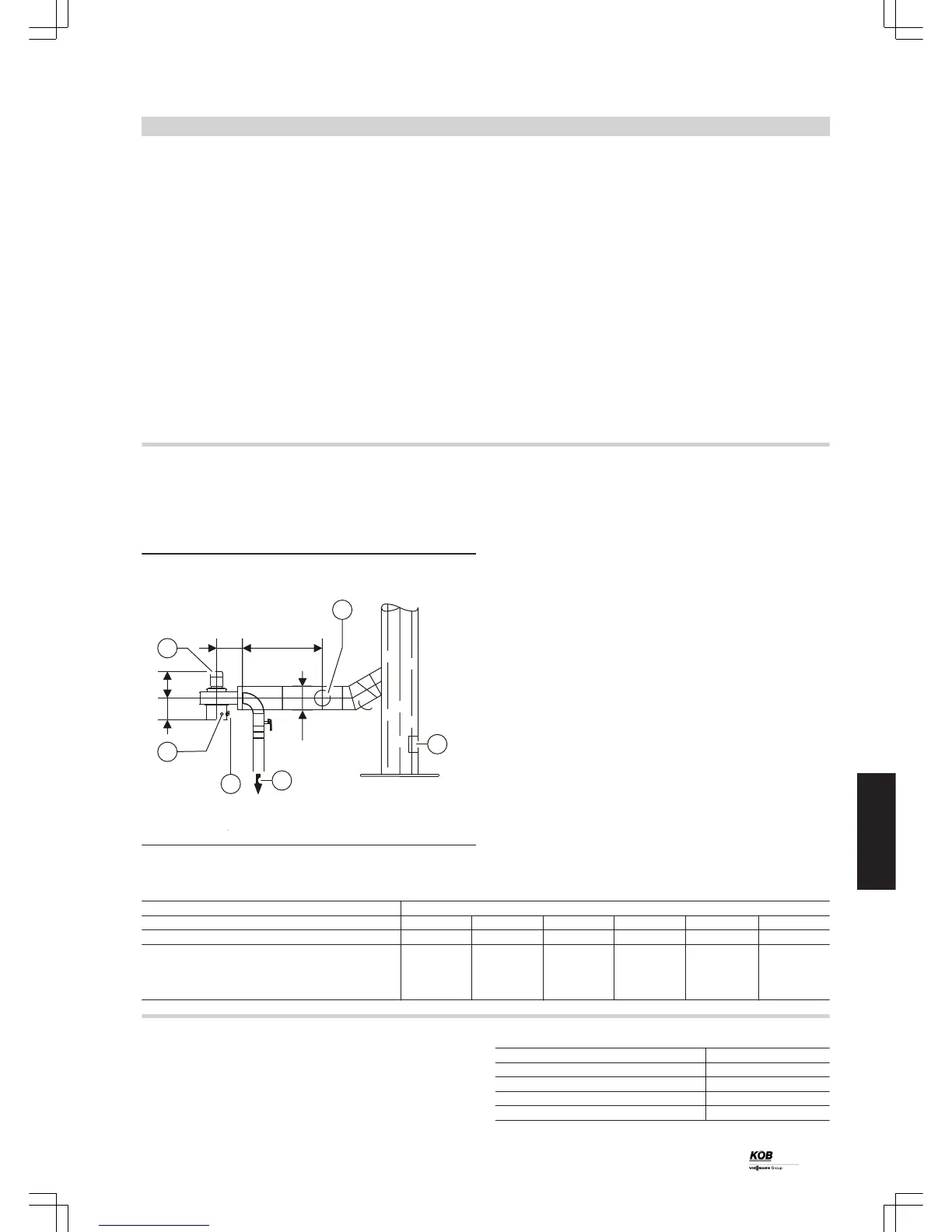
Observe the following when connecting the flue:
A
Draught limiter
B
Recirculation
C
Lambda probe with measured value transducer
D
Flue gas temperature sensor
E
Flue gas fan
■ Install the flue pipe rising to the chimney (with 45º if possible).
■ Never push the flue pipe too far into the chimney.
■ Ensure the full flue gas path (incl. cleaning aperture) is gas-tight.
■ Never seal the flue pipe into the chimney. Connect flue pipe with a
flexible flue pipe adaptor.
■ Provide a cleaning aperture.
■ Wall liners to adapt to flue systems by third party manufacturers.
■ Provide the flue with thermal insulation of at least 30 mm thickness.
Trade name Pyrot rotation combustion
Rated output kW 100 150 220 300 400 540
Part no.: 7423 656 7423 657 7423 658 7423 659 7423 660 7423 661
a mm 292 292 292 323 323 442
b mm 200 250 250 300 350 350
c mm 245 232 257 277 355 355
d mm 345 358 358 352 375 375
Flue gas routing (accessories)
Flue bend 0-90°
Version: black, without insulation
Flue bend 0-90° Part no.
D = 200 mm 7388 176
D = 250 mm 7388 169
D = 300 mm 7388 203
D = 350 mm 7387 424
Design information
(cont.)
PYROT
89
5822 516 GB
6