Max. permissible dumping height and length of the pushrods in S650
Trade name Pushrod
Type AS-2.50 AS-2.25 AS-2.0 AS-1.75 AS-1.5
Part no.: 7387 992 7387 995 7387 836 7387 956 7387 989
Dumping height with length:
12 m 1.5 1.8 2.0 2.4 2.9
10 m 1.9 2.3 2.6 3.1 3.7
8 m 2.6 3.0 3.5 4.2 4.9
6 m 3.7 4.3 4.9 6.1 7.4
Specification for the pushrod drives
Trade name Pushrod drive
Type Individual stand-
ard
Twin standard Heavy
version
Part no.: 7387 978 7387 915 on request
Piston diameter mm 180 180 220
Piston rod diameter mm 90 90 110
Lift mm 600 600 800
Test pressure bar 240 240 240
Pressure force at 190 bar FZD kN 484 484 722
Tensile force at 190 bar FZZ kN 362 362 542
Length from centre of cylinder - piston boss
mm
Type K
1080
Type L
1230
-
1575
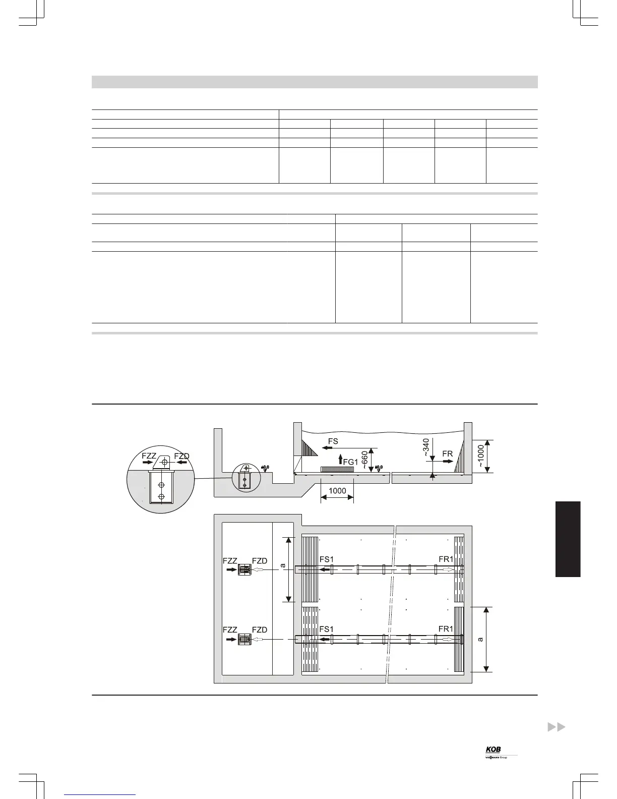
Forces on the building
In the case of pushrod drives for discharge push floors with several
pushrods, the hydraulic cylinders have pipes laid in opposite flow
directions, i.e. the first cylinder pulls, the second cylinder pushes, the
third cylinder pulls, etc. The cylinder with the lowest pressure drops
generally moves first into the end position, then the next one.
When all cylinders are in the end position, the oil pressure increases
up to the response pressure for the pressure diverter valve (set to 190
bar at the factory) and this switches to the opposite direction.
FG1 Maximum tensile force on the weld base of bunker upwards per
metre length
FS Total standard forces on the front panel (slot discharge)
FR Total standard forces on the back panel
FR1 Standard force of a pushrod on the back panel
FS1 Standard force of a pushrod on the front panel
Design information
(cont.)
PYROT
61
5822 516 GB
6