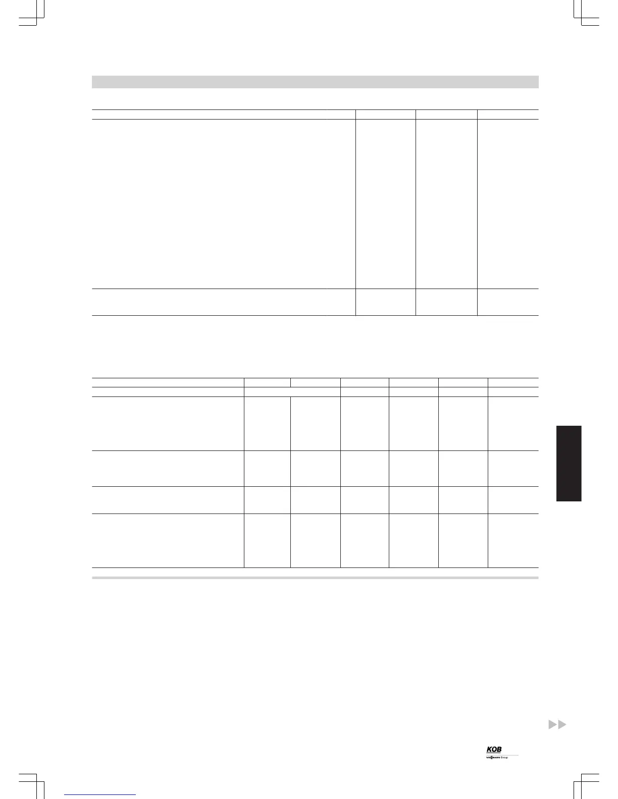
Dimensions
Rated output kW 220 300 400
Dimensions
a mm 1413 1413 1413
b mm 1833 1833 1833
c mm 460 460 460
d mm 300 300 350
e mm 2097 2097 2097
f mm 1720 1720 1720
g mm 2230 2230 2230
h mm 2820 2820 2827
k mm 1270 1270 1400
l mm 1670 1670 1717
m mm 1730 1730 1770
n mm 2255 2255 2400
o mm 840 840 840
p mm 900 900 900
q. mm 1192 1192 1040
r mm 1069 1069 1069
s mm 800 800 800
t mm 2200 2200 2200
Weight
Transport weight kg 470+470 470+490 490+490
Total weight kg 940 960 980
Note
Further dimensions on request.
Specification
Rated output kW 100 150 220 300 400 540
Part no. 7424 949 7423 697 7423 698 7423 699 7424 950
Suitable for continuous outputs of kW 24-80 41-135 60-200 80-270 100-360 144-480
Dust content in clean gas mg/Nm³ <20 <20 <20 <20 <20 <20
Volume of ash box l 2x45 2x45 4x45 4x45 4x45 6x45
Connection pressure drop Pa 1200 1200 1200 1200 1200 1200
Number of cartridges pce 3 4 6 7 8 12
Number of filter modules pce 1 1 2 2 2 3
Transport dimensions
Length mm 1103 1103 2200 2200 2200 3300
Width mm 1230 1230 1230 1230 1230 1230
Height mm 2100 2100 2100 2100 2100 2100
Sensor technology
Temperature sensor pce 2 2 2 2 2 3
Differential pressure cells pce 1 1 1 1 1 1
Electrical connections
Electrical connections total kW 13 13 13 13 13 13
Flue gas fan kW 2.2 2.2 2.2 3.0 4.0 4.0
Filter heating kW 9.0 9.0 9.0 9.0 9.0 9.0
Power consumption during cold
start
kW 4.5 4.5 4.5 4.5 4.5 4.5
Cleaning, pneumatic
The whole tubular heat exchanger is cleaned with periodic blasts of
compressed air during operation. The process of cleaning itself is car-
ried out in consecutive blasting of the individual sections. The ash is
removed from the heat exchanger pipes by means of an extremely
short but strong pressure pulse. The device is installed on the back of
the boiler. The compressor should preferably be installed in a cool
place in the boiler room.
The number of cleaning processes within a unit of time (e.g. per hour)
is matched accordingly to the boiler load. An individual, complete
cleaning process comprises a sequence of pressure pulses across all
sections of the heat exchanger.
Standard delivery:
■ Nozzle part integrated in the flue gas collector; incl. connectors with
heat deflection discs
■ Compressed air distributor with container and valves, with heat-
resistant hoses connected to the nozzle part
■ Compressor (rotation compressor) for local applications
– Supply output 160 l/min
– Container 90 l
– Pressure max.10 bar
– Motor 1.5 kW
–
1450 rpm
– 3 x 400 V
– Incl. pressure regulator and pressure switch
– Sound level 68 dB(A)
■ Compressed air hose up to max. 4.0 m length
Installation accessories
(cont.)
PYROT
37
5822 516 GB
5