Ethernet IP with RSLogix | 6 AKD Instructions
6 AKD Instructions
The AKD Add-On Instructions are RSLogix instructions that define AKD drives and axis configurations.
These instructions are made to be imported into an RSLogix5000 project. Once defined in a project, they func-
tion just as a native RSLogix Motion instruction. The add-on instructions are written to mirror the native
instructions, leveraging existing knowledge of the software. The add-on instructions encapsulate the most
commonly used logic for AKD axes. They provide easily reusable tools to operate drives and axes, promoting
consistency across different projects. They provide easy control of I/O Assembly Messages. The native
MSG instruction is used in RSLogix for sending Explicit Messages.
Only one AKD add-on instruction can be enabled at a time in your project. The add-on instructions write to
the same data structure (the Command Assembly) to set control bits and command motion. Trying to enable
or execute two add-on instructions at one time would create a conflict for the control of the communication
channel. Keep this in mind when writing programs that utilize these instructions.
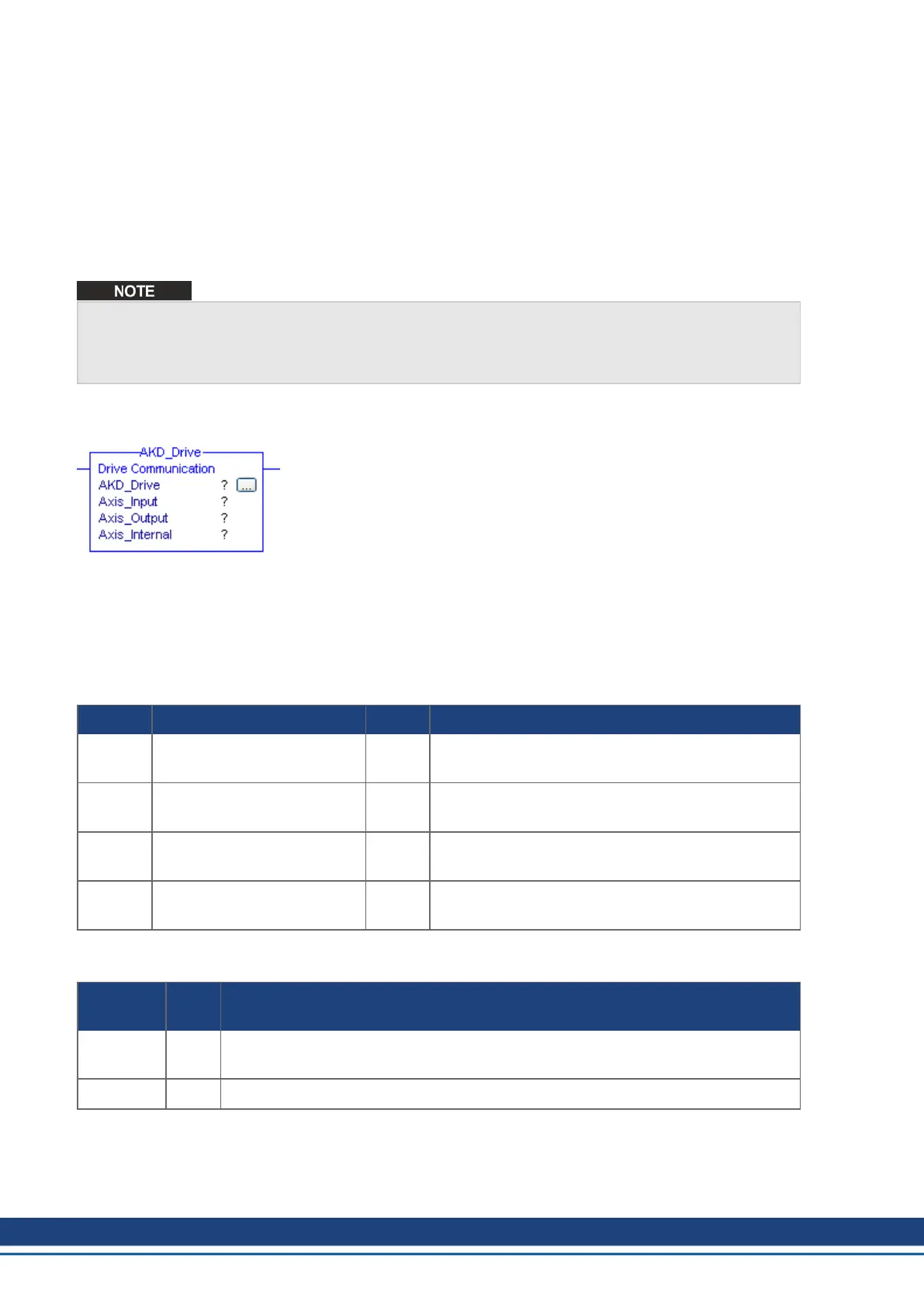
6.1 Motion Axis Drive Communication (AKD_Drive)
6.1.1 Description
Use the motion axis drive communication (AKD_Drive) instruction to initiate communication for an axis. This
command is required for all other AKD commands to function properly.
6.1.2 Operands
Operand Type Format Description
AKD_
Drive
AKD_DRIVE Tag Control tag for this instruction.
Axis_
Input
AB:ETHERNET_MODULE_
SINT_8Bytes:I:0
Tag Input memory space for axis.
Axis_
Output
AB:ETHERNET_MODULE_
SINT_8Bytes:O:0
Tag Output memory space for axis.
Axis_
Internal
AKD_AXIS Tag The name of the axis to initialize. This tag is an input
parameter for all AKD instructions.
6.1.3 AKD_DRIVEStructure
Mnemonic Data
Type
Description
.EnableIn BOOL The enable input bit indicates that the instruction is enabled. It remains set until the
instruction completes and the rung-condition-in goes false.
.EnableOut BOOL The enable output bit is the output of the enable input bit.
6.1.4 Execution
28 Kollmorgen | kdn.kollmorgen.com | November 2018

 Loading...


