3) Recall the Default panel setup (9).
4) Return to the Main Menu by pressing the Return push button (I0).
5) Call the Panel Status menu (2).
6)
Set CHAN 1 Fixed VOLTS/DIV as appropriate (27)
generator.
7) Adjust CHAN 1 VAR vernier (28) as appropriate
generator.
8) Set CHAN 1 OFFSET as appropriate.
9) Set CHAN 1 COUPLING to DC 50 Q
I0)
Adjust TRIGGRR DELAY control (34) to 20.0~ Pre.
11)
Adjust TRIGGER LRVEL control (33) to .00 division.
12)
Set TRIGGER COUPLING to AC (30).
13)
Set TRIGGER SOURCE to CHAN i (23).
14)
Set TRIGGER SLOPE to POS (25).
15) Arm the trigger by setting the TRIGGER MODE (29) to single.
16)
Set TIMEIDIV control (36) to 50 nsec/div (36).
17)
Set INTERLEAVED SAMPLING to OFF (37).
18) Set BANDW-IDTff LIMIT to OFF (50).
19) Return to the Main Menu by pressing the Return push button (10).
20) Set CHAN 1 to ON and CHAN 2 to OFF (49).
21) Set DUAL GRID mode to OFF (14).
22)
Now trigger the signal source.
match the
match the
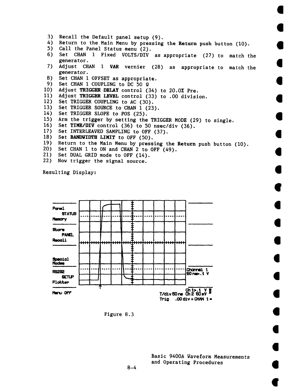
Resulting Display:
...... ,......o ...o ...., ¯
!ll
¯ ,,,,,.,,i.,,.,,,..i,..,i.,..i f,,. l,,,,i,,,.lq,,,,
...... Cl’mr~l ’J,
50 rm~.1 V
Figure 8.3
8-4
Basic 9400A Naveform Measurements
and Operating Procedures