55
LeeBoy Model 8515D Conveyor Paver 5-19
Maintenance
The other block in the center is used as a wire junction
block only. Refer to the wiring schematics in Section 6
to see where connections are made.
NOTE: Control boxes are manufactured to t all
screed and paver combinations. If not all
plugs are connected to wires, it may be
normal. Be sure to keep open plugs with the
plug terminator(s).
Any element lead can be plugged into any supply plug
under the heating control/distribution box. All six plugs
are equally rated.
• Each element output consists of two wires--one
connects to the L-1 circuit and the other to the L-2
circuit. (Figure 5-24)
• Each breaker has two terminals--one is connected
to the main input and the other terminal to an element
output wire.
• The L-1 circuit is the left bank of element breakers.
• The L-2 circuit is the right bank of element breakers
and wired slightly different. Each leg goes from the
main L-2 power lead through a breaker, then through
one of the six contacts on the element relays.
It is these relays that “make” or “break” the circuit to
each element to start or stop the heating cycles.
When the HEAT ON button is depressed, 12VDC is
momentarily applied to this terminal to start the timer
cycle. During the timer cycle, power will not be applied
to this terminal unless the HEAT ON button is depressed
again.
There are six terminals on the timer:
• The top two left terminals are the main 12VDC input
terminals.
• The ground is on the left.
• The power is on the right.
• The top right terminal is the common terminal to the
internal timer relay that controls the heat system.
When power is applied to the input terminal, it is also
jumped to the common (or COM) terminal on the timer.
• The lower right two terminals on the timer are the
outputs of the internal timer relay.
Screed Electric Heat
(Option)
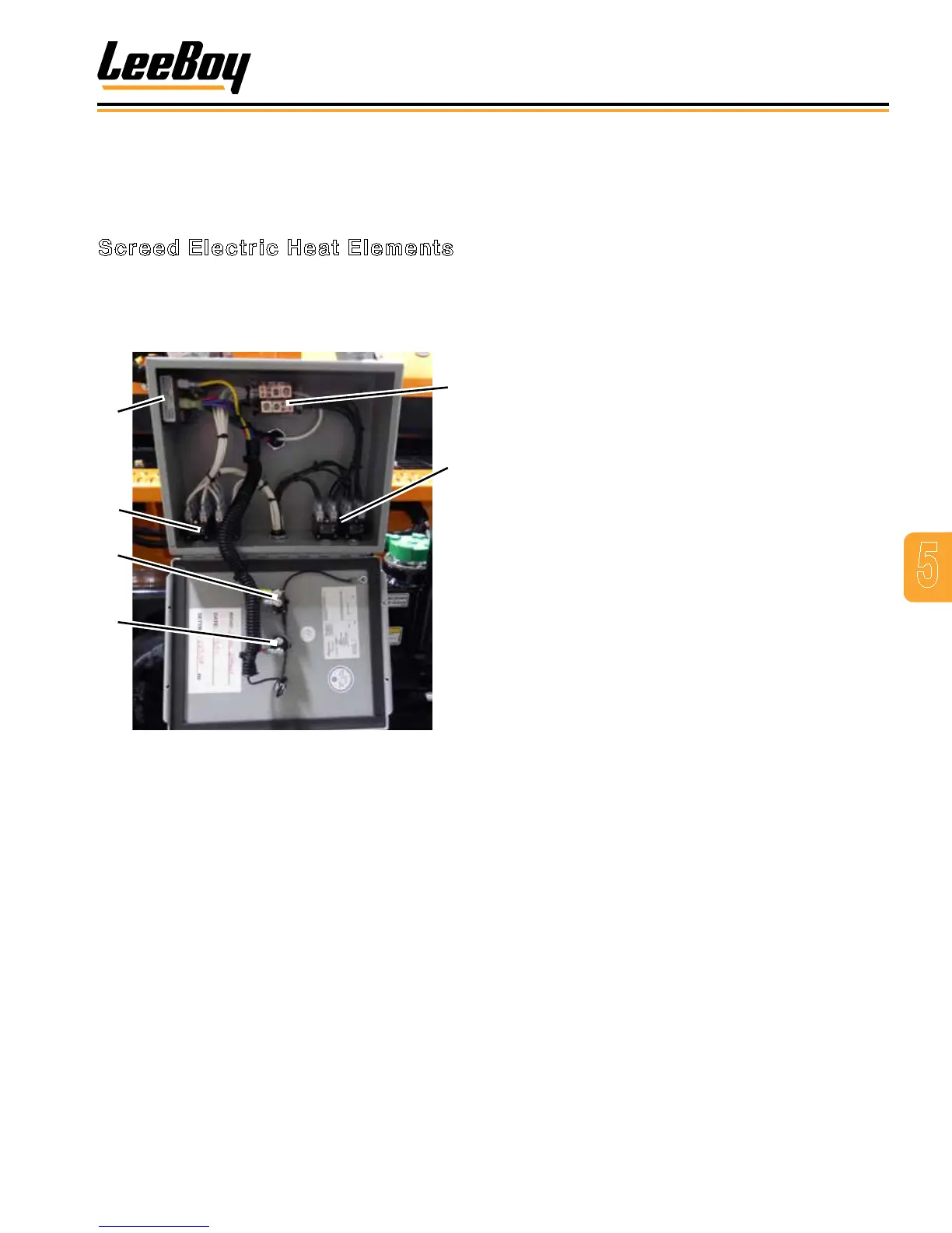
Screed Electric Heat Elements
The electric heat control box contains the element
breakers and main outputs for the screed heating
system. Powered by 220VAC and 240VAC, each
element has two breakers. (Figure 5-24)
1
2
5
6
3
4
Figure 5-24. Electric Heat Elements
1 - Timer
2 - L-1 Circuit Breakers
3 - Power On Toggle
4 - Heat On Button
5 - Wire Junction Block
6 - L-2 Circuit Breaker
The control box consists of three major types of
components:
• The system timer is located in the upper left hand
corner of the box.
• The element breakers are located in the lower surface
of the box.