5-10 LeeBoy Model 8515D Conveyor Paver
Maintenance
Track Tension Pressure Relief
The hydraulic adjustment cylinders are automatic and
provide even tension on the tracks to prevent excessive
wear to the paver’s undercarraige. The track tension
main manifold is mounted on the back side of the lower
hydraulic tank in the conveyor bed.
The track hydraulic pressure is set at 1500 PSI at the
track tension main manifold.
To check pressure, locate the track tension main
manifold in the conveyor bed and perform the following
procedures:
1. Raise conveyor bed. (Page 5-4)
2. Connect a 2000 PSI gauge inline with either Port
A or Port B on the track tension main manifold.
(Figure 5-10)
3. Place a Porta Power between the front idler and
frame to release pressure on the idler.
4. Increase the Porta Power pressure until the front
idler cylinder compresses.
5. Pressure should read 1500 PSI.
6. If the pressure is not correct, remove cap on the
relief cartridge valve. Using an allen wrench, adjust
the relief cartridge valve IN for more pressure or
OUT for less pressure until the PSI gauge reads
1500 PSI.
7. When the pressure guage reads 1500 PSI,
disconnect Porta Power and gauge.
Do not tamper with the adjustment
part of the relief cartridge valve.
Relief
Cartridge
Valve
Port B
Port A
Figure 5-10. Track Tension Main Manifold
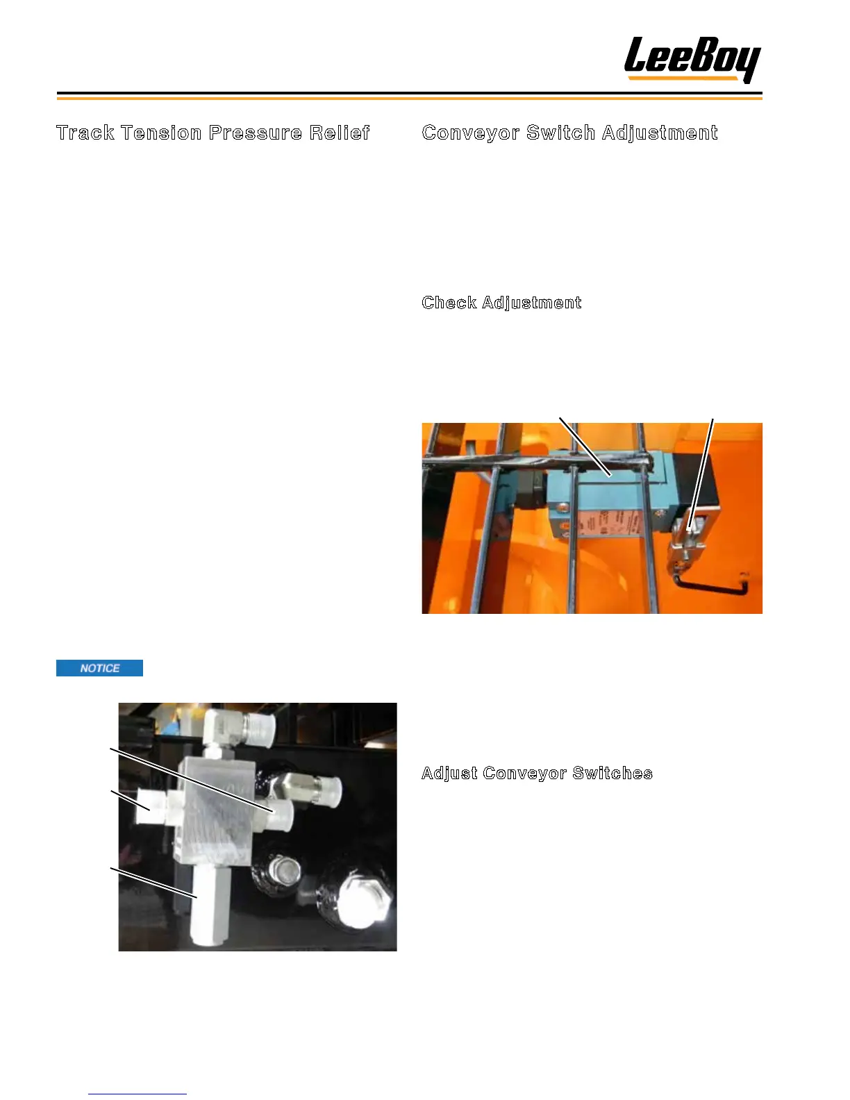
Conveyor Switch Adjustment
Small adjustments may be necessary to conveyor
switch for optimum conveyor performance. (Figure
5-11)
There are two positions of the conveyor ap: One upper,
shutting the conveyor OFF; and one lower, turning the
conveyor ON.
Check Adjustment
1. Remove the upper walkboard grate.
2. Raise the conveyor ap 6-1/2 to 7 inches (16.5 to
17.8 cm) from the bottom of the tank mount support
and insert the safety prop.
Conveyor Switch
Actuator Arm
Figure 5-11. Conveyor Switch Location
3. Secure conveyor ap so it remains in this position.
4. Check the conveyor switch.
5. If the switch clicked OFF, no further adjustment is
required to the upper ap.
Adjust Conveyor Switches
If the conveyor switch did not click OFF, adjustment is
needed:
1. Remove the linkage attaching the actuator arm to
the eyelet on the ap pivot housing.
2. Loosen Setscrew A on the actuator arm. (Figure
5-12)
3. Reposition this arm by either rotating it clockwise
or counterclockwise, depending upon where the
conveyor switch clicked OFF during the conveyor
ap upward travel.
4. When the switch clicks OFF, tighten setscrew and
reconnect linkage.