4
LeeBoy 8515D Conveyor Paver 4-21
Operation
NOTE: Adjust the pressure regulator valve IN or OUT
until the propane pressure regulator gauge
reads 15 pounds.
NOTE: It may be necessary to maintain low heat on
the screed if paving on a cool, windy day.
Reduce pressure on the propane pressure
regulator gauge to two pounds (.14 bar) in
these conditions. DO NOT attempt to regulate
the burner with the burner valve.
After the main screed (and screed extension) has
heated for 15 minutes:
1. Turn the propane tank valve clockwise to the
CLOSE position to allow the propane system to
burn off all the gas. (Figure 4-33)
2. When the ames extinguish, TURN OFF ALL burner
valves clockwise to the OFF position. (Figures
4-32 through 4-35)
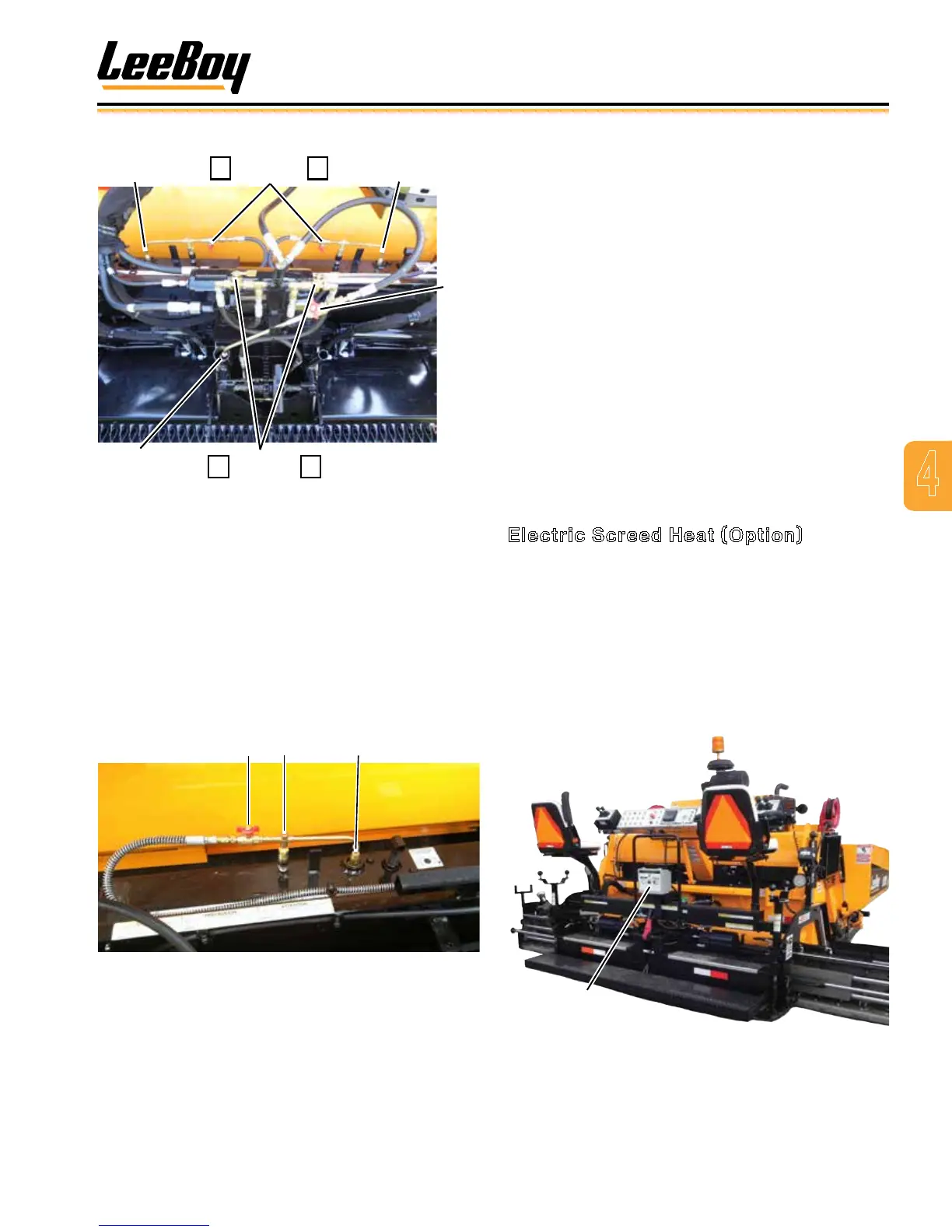
Electric Screed Heat (Option)
The LeeBoy 8515D Conveyor Paver offers an optional
electric heat system to heat the screed, including the
screed extensions, in lieu of the burner system. A
hydraulically-driven generator powers the electric heat
control box mounted in the center on the rear side of the
machine. This control box is where you will select the
heating function before you begin to pave. It is easily
accessible to the screed operator when a heating cycle
is needed. (Figure 4-36).
Electric
Heat
Figure 4-36. Electric Heat Control Box
Extension
Ignitor
Extension
Ignitor
Extension
Ignitor Valves
Main
Ignitor
Main Burner
Valves
Main
Valve
2 3
4 5
Figure 4-34. Screed Burner Valves
When using the screed extension(s), light the screed
extension(s) after the main screed burner has been lit
following these additional steps (Figure 4-35):
5. Lift up on the burner coupler to release ignitor.
6. Lift ignitor wand, turn valve counterclockwise to
the OPEN position and light the ignitor end with the
torch striker.
7. Replace the lit ignitor wand into the burner cradle.
8. Push down on burner coupler back into place.
1 32
Figure 4-35. Extension Burner
1 - Extension Ignitor Wand Valve
2 - Burner Coupler
3 - Burner