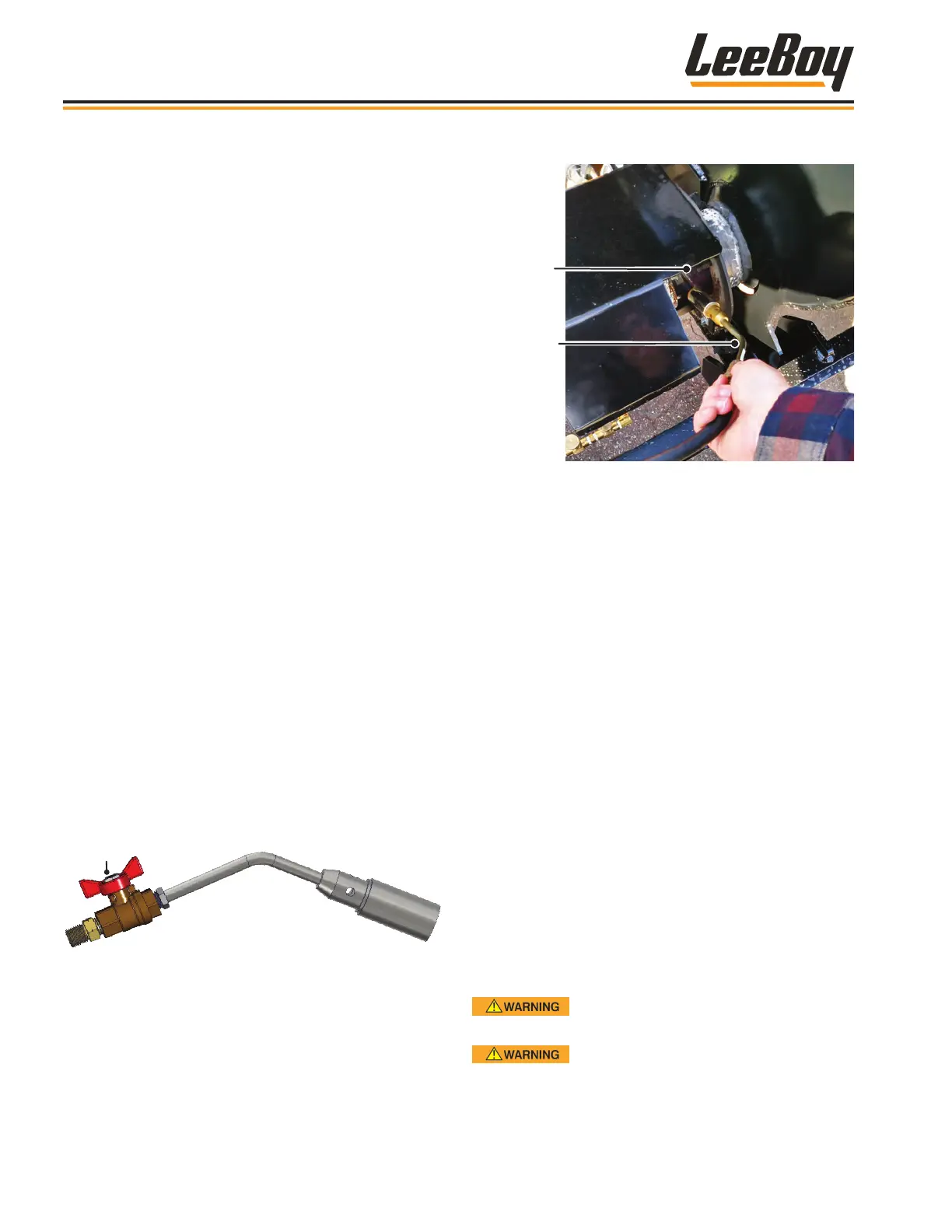
8. Light ignitor using a torch striker. (Figure 4-11)
Ignitor
Wand
Burner
Ignition Tube
Figure 4-11. LPG Burner Ignitor
9. Hold the lit ignitor wand at the burner ignition tube at
the burner as shown in Figure 4-11.
10. If it doesn’t light immediately:
• Shut off the gas ow by turning the shut-off valve
clockwise. (Figure 4-9 on Page 4-13)
• Wait 30 seconds to allow pockets of trapped gas
to purge.
• Repeat this p
1
rocedure until burner is lit.
11. After the burner is lit, close the wand ignitor valve by
turning it clockwise. (Figure 4-10)
12. Fully open the shut-off and pilot valves by turning
them clockwise. (Figure 4-9)
13. Return ignitor wand to its storage bracket.
14. Monitor the asphalt temperature gauge to
ensure the liquid asphalt is heated to the desired
temperature according to material specications .
This should NEVER exceed 180° F (82° C). (Figure
4-9)
NOTE: Monitor the temperature several times while
working.
15. After asphalt has reached the appropriate
temperature, start the engine. (Page 4-4)
Never start the engine unless there is
enough tack material circulating in the system.
DO NOT heat emulsied asphalt
more than 185° F (29.9° C). Elevated temperatures
evaporate the water and will produce an asphalt
layer inside the tank that will be difcult to remove.
3. Ensure ALL valves on the unit are in the OFF
position. (Refer to Page 3-6 and 3-7, Valve
Controls.)
• Propane tank valve.
• Fuel valve (diesel burner only).
• Pilot valve.
• Shut-Off valve.
• Ignitor wand valve.
• Liquid asphalt valves.
• Flush valve.
• Circulating valve.
• Spray wand valves.
• Sampling valve.
• Spray bar valves, if equipped with this option.
4. Open the propane tank valve to start the propane
gas ow by turning valve counterclockwise. (Figure
4-9)
5. Regulate the propane pressure to 15 - 17 PSI
(maximum) by adjusting knob on the regulator.
(Figure 4-9)
• Turn regulator knob clockwise to increase
pressure.
• Turn regulator knob counterclockwise to
decrease pressure.
6. Turn the shut-off valve counterclockwise to allow
gas ow to the burner. (Figure 4-9)
7. Remove the ignitor wand from its stowed position
and open its valve by turning counterclockwise.
(Figure 4-10)
Figure 4-10. Ignitor Wand Valve
Operation
L300 and L600 Tack Distributors4-14